
Energy-saving gas stove

A gas stove, energy-saving ring technology, applied in heating fuels, household stoves/stoves, stove/stove tops, etc., can solve the problems of heat use environment temperature rise, loss of energy utilization efficiency, and adverse health of users, etc. Achieve the effect of increasing heat exchange time, preventing heat transfer to the outside, and reducing the effect of temperature rise

Inactive Publication Date: 2014-07-23
CHENGDU ZHONGCHENG TECH
View PDF10 Cites 3 Cited by
  • Summary
  • Abstract
  • Description
  • Claims
  • Application Information

AI Technical Summary

Problems solved by technology

The loss of heat results in low energy utilization efficiency. At present, the thermal efficiency of household stoves is generally between 50% and 60%.
Moreover, the loss of heat also causes the temperature of the use environment to rise, which is not conducive to the health of users.

Method used


Image

  • Energy-saving gas stove
  • Energy-saving gas stove
  • Energy-saving gas stove

Examples


Embodiment 1

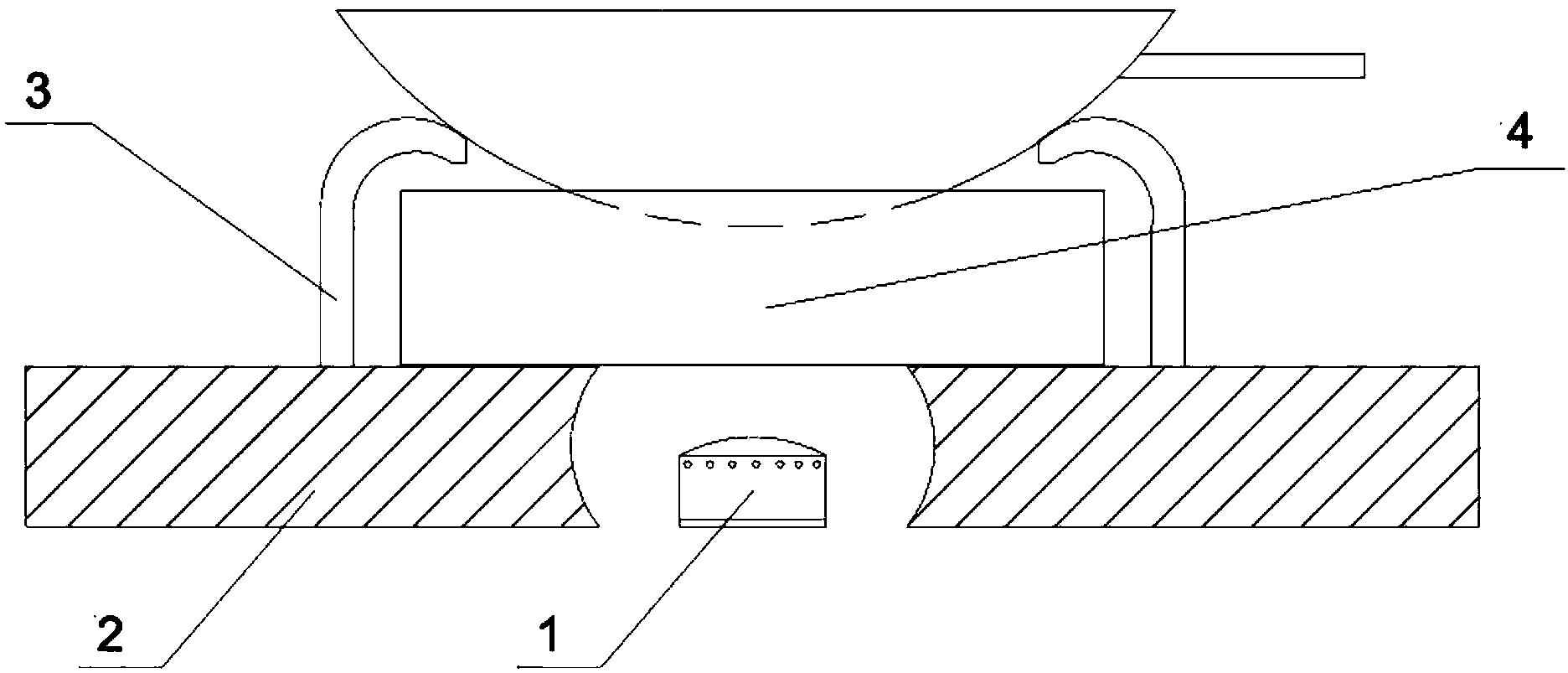
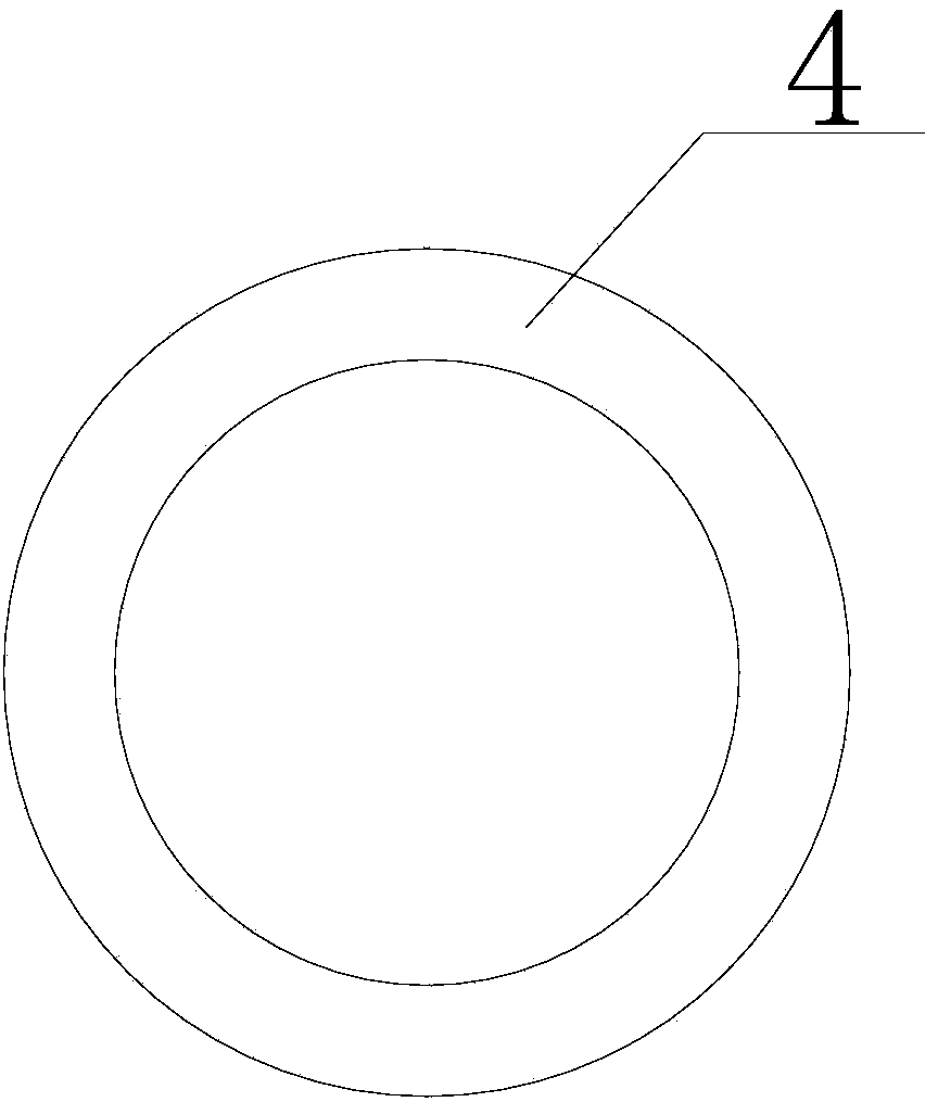
[0026] Such as figure 1 with figure 2 As shown, an energy-saving gas stove includes a stove top 1, a gas stove panel 2, a bracket 3 and an energy-saving ring 4. For the bracket 3 that supports the pot, an annular energy-saving ring 4 is installed on the inner ring of the bracket 3. The height of the energy-saving ring 4 is lower than the bracket 1, so that the pot can be smoothly placed in the pot bracket and removed from the pan bracket. Take it out, and leave a certain distance between the energy-saving ring 4 and the bottom surface of the pot to ensure the circulation of the gas field. The energy-saving ring 4 is made of heat-resistant and heat-insulating material, which includes aluminum silicate ceramic fiber, and the heat-resistant and heat-insulating material is used to insulate heat radiation from spreading outwards, improve thermal efficiency, save energy and protect the environment, and reduce the impact of flames on the stove and Influenced by the temperature ris...

Embodiment 2

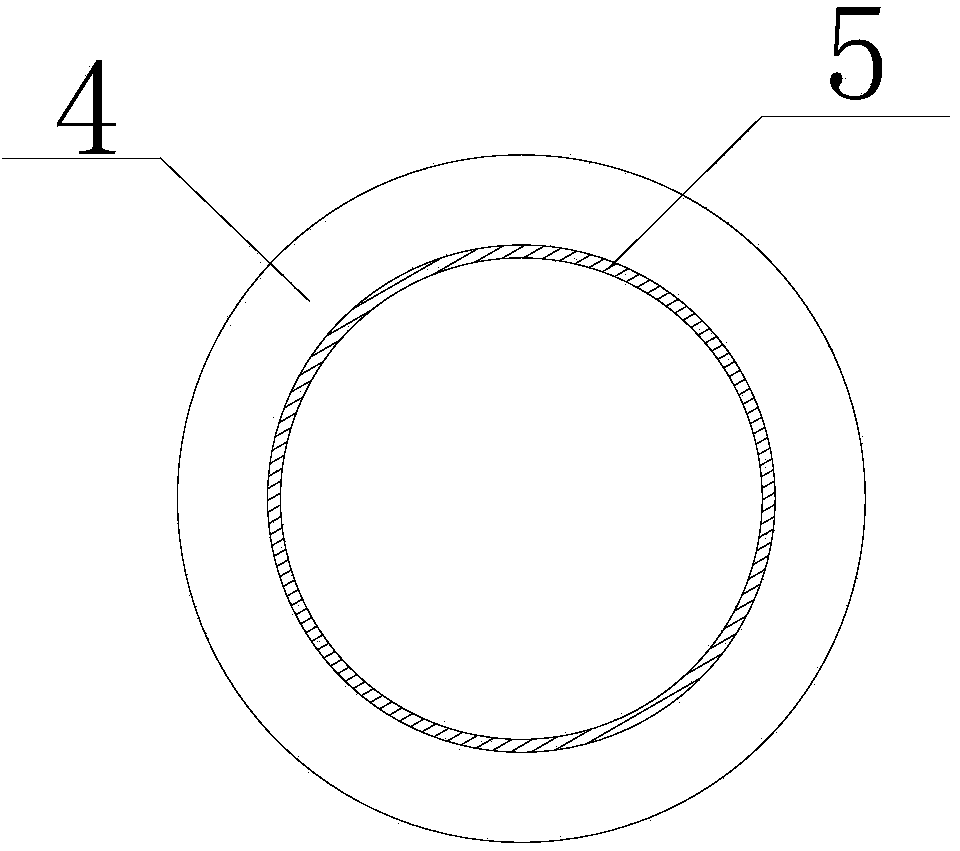
[0028] Such as image 3 As shown, a heat-resistant reflective layer 5 is provided on the inner ring of the annular energy-saving ring 4 made of heat-resistant and heat-insulating material, and the heat-resistant reflective layer 5 can concentrate the heat radiation energy and improve thermal efficiency.

Embodiment 3

[0030] Such as Figure 4 As shown, an energy-saving gas cooker includes a burner head 1, a gas cooker panel 2, a bracket 3 and an energy-saving ring 4, an annular energy-saving ring 4 is installed on the inner ring of the bracket 3, and a foot is provided at the bottom of the energy-saving ring 4 6 frames are installed on the gas cooker panel 2, the height of the energy-saving ring 4 is lower than the support 1, and there is a certain distance between the energy-saving ring 4 and the bottom surface of the pot.

[0031] Due to the function of the feet 6, a gap is formed between the energy-saving ring 4 and the panel 2 of the gas stove. This gap is a passage for supplementing combustion-supporting air, which can make the gas burn more fully, avoid the generation of carbon monoxide, improve the release of gas combustion energy, and improve thermal efficiency. .


PUM


Abstract

The invention discloses an energy-saving gas stove, which comprises a burner, a gas stove panel, a bracket and an energy saving ring. The energy-saving gas stove is characterized in that the burner is arranged in a burner installing hole formed in the gas stove panel; a bracket for supporting cookware is mounted above the gas stove panel; the annular energy saving ring is arranged at the inner ring of the bracket; the height of the energy saving ring is less than that of the bracket, so that the cookware can be smoothly placed on or taken out of the bracket; a certain space is remained between the energy saving ring and the bottom surface of a wok, so that the gas can be sufficiently combusted. According to the energy-saving gas stove, a ring body with annular structure is made of thermal resistant and insulating material, so that the heat energy loss caused by heat radiation of the gas stove flame and heat dissipation of air convection is greatly reduced, the heat efficiency is remarkably increased and the energy is saved.

Description

technical field [0001] The invention relates to a gas cooker, in particular to an energy-saving gas cooker. Background technique [0002] Gas stoves are kitchen utensils that are directly heated by gaseous fuels such as liquefied petroleum gas, artificial gas, and natural gas. No one knows how popular it is. When the gas stove is working, the gas enters the stove from the intake pipe, enters the burner after the flow is adjusted by the gas valve, and mixes with the air at the same time. The mixed gas is ejected from the fire hole of the fire distributor and is ignited by the ignition device to form a flame. Used to heat cookware placed on pot supports. [0003] Energy conservation is an important thing that benefits the country and the people, and various energy-saving products continue to emerge in all walks of life. In the gas cooker industry, various manufacturers are also constantly proposing various forms of energy-saving product series. For example, Vantage's i1001...

Claims


Application Information

Patent Timeline
Patent Type & Authority Applications(China)
IPC IPC(8): F24C3/00F24C15/10
CPCY02B40/00
Inventor 谢玲
Owner CHENGDU ZHONGCHENG TECH
Learn More