Al technical title is built by PatSnap Al team. It summarizes the technical point description of the patent document.
An iron driller and bracket technology, which is applied to drill pipes, drill pipes, drilling equipment, etc., can solve the problems of large thread damage of drilling tools, high labor intensity and narrow range of drilling tools, so as to avoid equipment replacement and maintenance. The number of times, the high degree of automation, the effect of reducing the production cost
Active Publication Date: 2017-02-15
RG PETRO MACHINERY GROUP
View PDF7 Cites 0 Cited by
Summary
Abstract
Description
Claims
Application Information
AI Technical Summary
This helps you quickly interpret patents by identifying the three key elements:
Problems solved by technology
Method used
Benefits of technology
Problems solved by technology
These mechanized equipment still need manual operation at the wellhead, the labor intensity is very high, the safety of the operators cannot be effectively guaranteed, and the labor cost also increases accordingly
As far as the above-mentioned equipment itself is concerned, the speed of connecting and dismounting the drilling tools is slow, which directly affects the efficiency of drilling and workover; at the same time, these equipments are suitable for a narrow range of drilling tools, and cannot adjust the make-up and breakout torque and breakout torque according to real-time conditions. stroke, the thread of the drilling tool is greatly damaged, and as a result, it needs to be replaced frequently, which makes the connection, disassembly and maintenance of the drilling tool more inconvenient
Method used
Image
Click on the blue label to locate the original text in one second.
Reading with bidirectional positioning of images and text.
Examples
Embodiment Construction
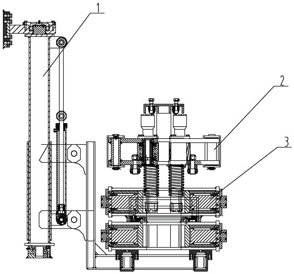
[0014] see figure 1 As shown, an iron driller includes a rotary bracket 1, a turnbuckle pliers 2 and a cracking pliers 3, the rotary bracket 1 carries the cracking pliers 3, and a twisting pliers is arranged above the cracking pliers 2.
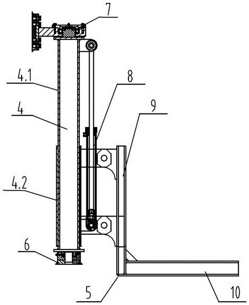
[0015] see figure 2 As shown, the rotary bracket of the iron driller includes: a column 4, an L-shaped bracket 5, a rotating base 6, a rotating gear 7, and a lifting hydraulic cylinder 8. The column 4 is composed of an inner square pipe 4.1 and an outer tube 4.2, the outer tube 4.2 is slidably sleeved on the outer wall of the inner tube 4.1, the upper and lower ends of the inner tube 4.1 are provided with a rotating base 6, and the upper end of the inner tube 4.1 is equipped with a rotating base 6 There is also a rotating gear 7 that can drive the inner square tube 4.1 to rotate. The L-shaped bracket 5 is composed of a vertical support plate 9 and a horizontal support plate 10. The vertical support plate 9 is fixed on the outer wall of the...
PUM
Abstract
The invention discloses an iron roughneck. The iron roughneck comprises a rotary bracket, a pair of buckle collapsing pliers and a spinning wrench. The rotary bracket comprises a stand column, an L-shaped bracket body, a rotating base, a rotating gear and a lifting hydraulic cylinder. The pair of buckle collapsing pliers comprises a rotating shaft assembly, a hydraulic clamping pliers assembly, a rotating shaft base, a rotating hydraulic cylinder assembly and a rotating and guide pushing hydraulic cylinder assembly. The spinning wrench comprises a support, a first rocker arm, a second rocker arm, a first connecting frame rod, a second connecting frame rod, a first roller wrench assembly, a second roller wrench assembly, a clamping hydraulic cylinder, a first balancing connecting rod, a second balancing connecting rod and a balancing pin roll. Compared with the prior art, the iron roughneck is complete in function, compact in structure and high in automation degree, saves manpower, lowers production cost, enables buckle assembly and buckle disassembly to be mechanized, improves the working efficiency, and meanwhile can further adjust the buckle assembly and disassembly torque and buckle assembly and disassembly thread travel compensation, protect drill rod threads, and reduce the frequency of equipment replacement and maintenance.
Description
technical field [0001] The invention relates to the technical field of drilling rigs, in particular to an iron driller used for drilling or repairing wells. Background technique [0002] At present, in oil drilling and workover operations, the connection and disassembly of drilling tools during the tripping process is basically done manually with the help of some mechanized equipment, such as hydraulic tongs, cat heads, pneumatic spinners, etc. . These mechanized equipment still need to be manually operated at the wellhead, which is very labor intensive, the safety of the operators cannot be effectively guaranteed, and the labor cost also increases accordingly. As far as the above-mentioned equipment itself is concerned, the connection and disassembly speed of drilling tools is slow, which directly affects the efficiency of drilling and workover; at the same time, these equipments are suitable for a narrow range of drilling tools, and cannot adjust the make-up and break-out...
Claims
Application Information
Patent Timeline
Application Date:The date an application was filed.
Publication Date:The date a patent or application was officially published.
First Publication Date:The earliest publication date of a patent with the same application number.
Issue Date:Publication date of the patent grant document.
PCT Entry Date:The Entry date of PCT National Phase.
Estimated Expiry Date:The statutory expiry date of a patent right according to the Patent Law, and it is the longest term of protection that the patent right can achieve without the termination of the patent right due to other reasons(Term extension factor has been taken into account ).
Invalid Date:Actual expiry date is based on effective date or publication date of legal transaction data of invalid patent.