
Rod reducing die with floating centralizing structure

A bar material and mold technology, which is applied in the field of bar material reducing molds, can solve the problems of operator injury and safety hazards, and achieve the effect of eliminating safety hazards

Pending Publication Date: 2019-01-25
江苏理研科技股份有限公司
View PDF7 Cites 0 Cited by
  • Summary
  • Abstract
  • Description
  • Claims
  • Application Information

AI Technical Summary

Problems solved by technology

It can be seen that there is a huge potential safety hazard in the reducing die in the prior art, and it is very easy to cause injury to the operator when the die is out of control due to a fault

Method used


Image

  • Rod reducing die with floating centralizing structure
  • Rod reducing die with floating centralizing structure

Examples


Embodiment Construction

[0020] In order to make the above objects, features and advantages of the present invention more comprehensible, the present invention will be further described in detail below in conjunction with the accompanying drawings and specific embodiments.

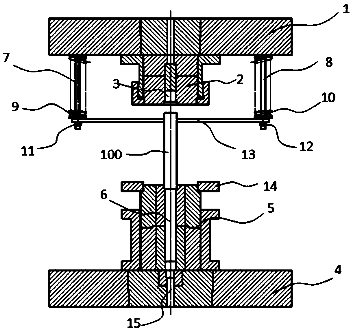
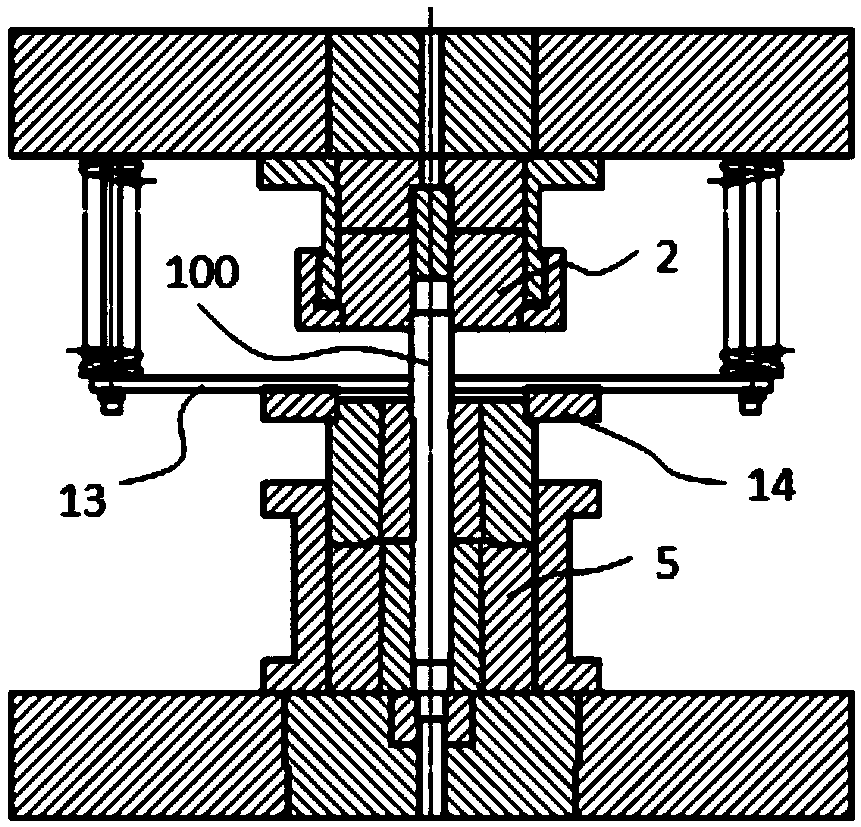
[0021] Such as figure 1 and figure 2 As shown, the bar reducing die provided by the present invention has a floating centralizing structure, which includes an upper template 1, an upper mold 2, a lower template 4, a lower mold 5, and a floating centralizing structure. in:

[0022] The upper mold 2 is connected below the upper template 1 , and an upper diameter-reducing mold cavity 3 is formed in the upper mold 2 . The lower mold 5 is connected above the lower template 4 and is positioned directly below the upper mold 2, and is formed in the lower mold 5 towards the upper reducing die cavity 3 and is the same as the upper reducing die cavity 3. The lower diameter reducing die cavity 6 of the shaft.

[0023] The floating center...


PUM


Abstract

The invention provides a rod reducing die with a floating centralizing structure, comprising an upper die, a lower die and the floating centralizing structure, wherein an upper reducing cavity is formed in the upper die, and a lower reducing die facing the upper reducing cavity and coaxial to the upper reducing cavity is formed in the lower die. The floating centralizing structure includes springguide rods symmetrically connected to an upper die plate and positioned on two sides of the upper die, and a floating plate connected to the spring guide rods; the center of the floating plate is provided with a centralizing guide hole to centralize a rod to be reduced; the centralizing guide rod is coaxial to the upper reducing cavity and the lower reducing cavity; the floating plate can float upand down along the two spring guide rods to approach or leave the lower die. The rod reducing die with the floating centralizing structure can provide automatic centralizing for rods to be reduced, so that potential safety hazards due to manual centralizing are avoided.

Description

technical field [0001] The invention relates to the field of forging, in particular to a bar reducing die with a floating centering structure. Background technique [0002] In the forging process of long shaft parts, the bar as its blank usually needs to be reduced many times. Since the bar to be reduced is relatively long, an open die (the upper and lower dies are closed during the reduction process) is generally used for the reduction operation. [0003] The reducing die in the prior art is not equipped with a special bar straightening mechanism, therefore, in order to ensure that the upper end of the bar can accurately enter the upper reducing cavity of the upper die. After the bar is loaded into the lower reducing cavity of the lower die, the bar must be manually corrected so that the upper end of the bar is aligned with the upper reducing cavity in the upper die, and then the lower die is controlled to move downward until the upper end of the bar enters the upper reduc...

Claims


Application Information

Patent Timeline
Patent Type & Authority Applications(China)
IPC IPC(8): B21J13/02B21K1/06B21J13/08
CPCB21J13/02B21J13/08B21K1/06
Inventor 季成王大伟王荣波蔡冰蒋桂友李春风
Owner 江苏理研科技股份有限公司
Learn More