
Drilling tool salvaging device

A salvage device and drilling tool technology, which is applied to earth-moving drilling, wellbore/well components, etc., can solve problems such as time-consuming, difficult salvage methods, and easy deflection of drilling tools.

Inactive Publication Date: 2016-06-08
CHINA COAL SPECIAL DRILLING ENG +1
View PDF7 Cites 0 Cited by
  • Summary
  • Abstract
  • Description
  • Claims
  • Application Information

AI Technical Summary

Problems solved by technology

When the above-mentioned drilling rig performs the drilling operation, the drilling rig is erected on the ground, the lower end of the rotating shaft of the drilling rig is connected to the drilling tool, and the drilling rig starts to rotate the drilling tool, thereby implementing the drilling operation. The diameter of the drilled hole is the same as the diameter of the drilling tool. The diameters are basically the same. However, during the drilling process of the above-mentioned drilling rig, the drilling tool often swings greatly due to geological reasons, causing accidents where the drilling tool and the drilling rig fall off. If the salvage is not timely, the entire construction period will be delayed and the entire project progress will be affected. In the prior art, most of the fishing tools are salvaged by using suspension ropes and suspension hooks. However, in the above-mentioned fishing methods, when the drilling equipment is drilled at a deeper position below the ground, it is not only difficult to use the above-mentioned suspension hooks and suspension ropes Determine the position of the drilling tool, and the drilling tool is easily deflected during the lifting of the hook, which leads to the phenomenon that the drilling tool cannot be picked up at all. In this way, it is necessary to repeatedly lift and pull the drilling tool until the drilling tool is righted. The above-mentioned salvage method is extremely difficult and time-consuming

Method used


Image

  • Drilling tool salvaging device
  • Drilling tool salvaging device
  • Drilling tool salvaging device

Examples


Embodiment Construction

[0010] combine Figure 1 to Figure 5 , to further illustrate the present invention

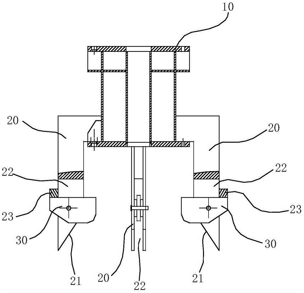
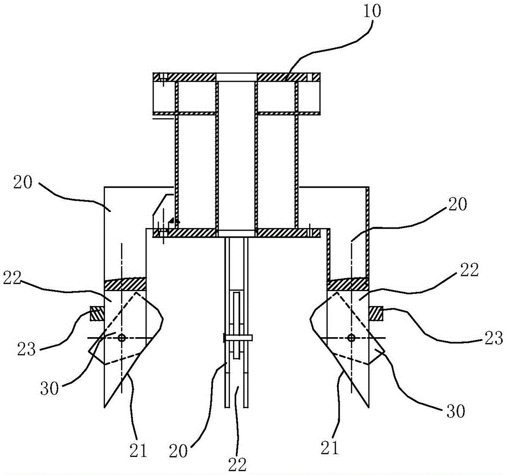
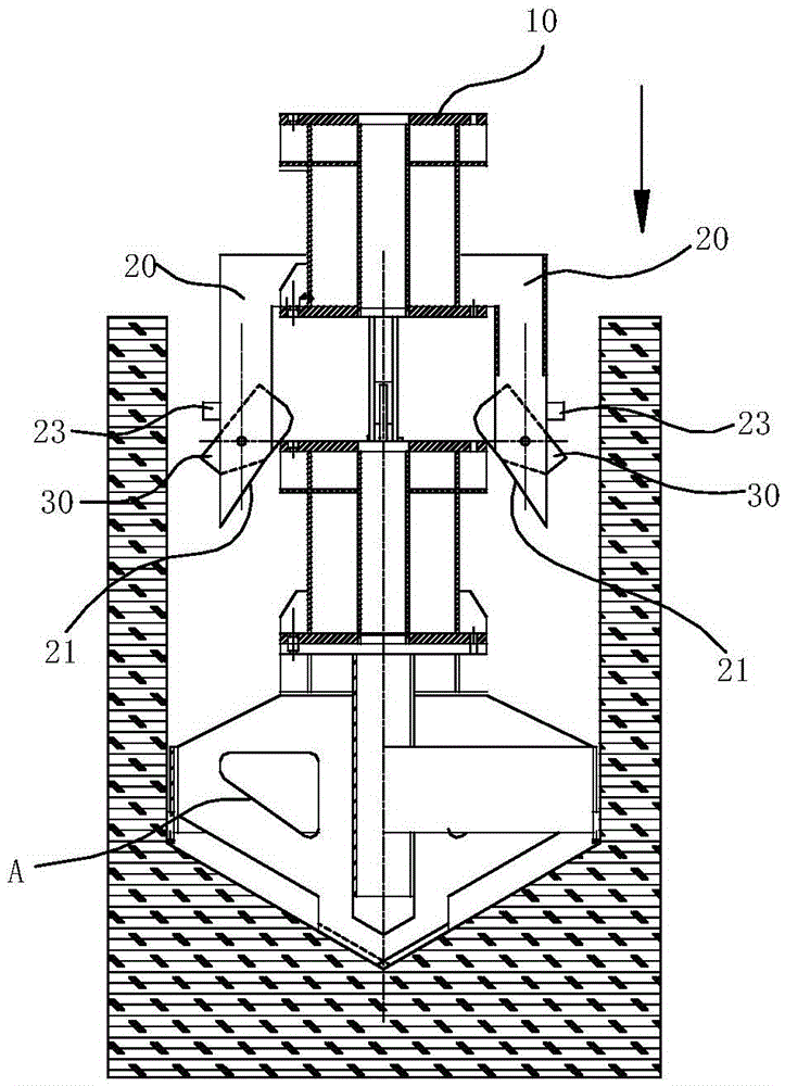
[0011] A drilling tool fishing device, comprising a counterweight plate 10, on which a cantilever 20 is distributed, and the cantilever 20 extends downward and parallel to the extending direction, and the area enclosed by the extension ends of the lower ends of the plurality of cantilevers 20 constitutes For the accommodation cavity of the drilling tool A to be salvaged, the lower extension end of the cantilever 20 is provided with a supporting part, and the supporting part is located on the cantilever 20 to accommodate and support the drilling tool A to be salvaged. The outer wall is also in two elevated positions. The counterweight plate 10 is connected to a lifting rod, and the lifting rod drives the lifting action of the counterweight plate 10 .

[0012] Abandon the disadvantages brought by the salvage method of using the salvage rope and the hook in the prior art, and use the lifting rod...


PUM


Abstract

The invention relates to a drilling tool salvaging device which comprises a counterweight disc. Cantilevers are distributed on the counterweight disc and downwards extend, the extending directions of the cantilevers are parallel, a region enclosed by the extending ends of the lower ends of the cantilevers forms a containing cavity of a drilling tool to be salvaged, the extending ends of the lower ends of the cantilevers are provided with supporting portions, the supporting portions located on the cantilevers are in the two positions states of containing the drilling tool to be salvaged and avoiding and supporting the outer wall of the drilling tool to be salvaged in a lifting mode, the counterweight disc is connected with a lifting rod, and the lifting rod drives the lifting actions of the counterweight disc. Accordingly, rigid connection between the drilling tool to be salvaged and the counterweight disc is achieved through the lifting rod, the drilling tool salvaging device downwards explore a drill hole until the cantilevers make contact with the dropped drilling tool, the drilling tool is automatically guided into the containing cavity formed by the cantilevers in an enclosing mode, the lifting rod is driven to rise, the supporting portions arranged at the extending ends of the lower ends of the cantilevers support the drilling tool, and then the drilling tool is lifted up and salvaged out of the drill hole; the drilling tool is movably located on the supporting portions, automatic righting of the drilling tool can be achieved, and therefore the drilling tool can be conveniently salvaged from the drill hole.

Description

technical field [0001] The invention relates to the technical field of engineering machinery, in particular to a drilling tool fishing device. Background technique [0002] During the construction of some bridges and highways, it is necessary to drill holes on the ground or underwater. According to different geological characteristics and structural strength requirements, the depth of the holes varies. Use the drilling tools on the drilling rig to perform the drilling operation. A good borehole is lowered into a reinforcement cage, and then concrete is poured to form a bored pile. When the above-mentioned drilling rig performs the drilling operation, the drilling rig is erected on the ground, the lower end of the rotating shaft of the drilling rig is connected to the drilling tool, and the drilling rig starts to rotate the drilling tool, thereby implementing the drilling operation. The diameter of the drilled hole is the same as the diameter of the drilling tool. The diamet...

Claims


Application Information

Patent Timeline
Patent Type & Authority Applications(China)
IPC IPC(8): E21B31/12
CPCE21B31/12
Inventor 曹化春王宗金郭圣旵魏红兵杨光亓燕秋魏延平荣怀宇王明思李公生付新鹏易鹏李奕张绍峰邓虎刘勇
Owner CHINA COAL SPECIAL DRILLING ENG
Learn More