Photovoltaic inverter and power-on self-testing method thereof
A photovoltaic inverter, power-on self-test technology, applied in photovoltaic power generation, instruments, measurement of electrical variables, etc., can solve problems such as rising costs, and achieve the effect of low current state
- Summary
- Abstract
- Description
- Claims
- Application Information
AI Technical Summary
Problems solved by technology
Method used
Image

Examples
Embodiment 1
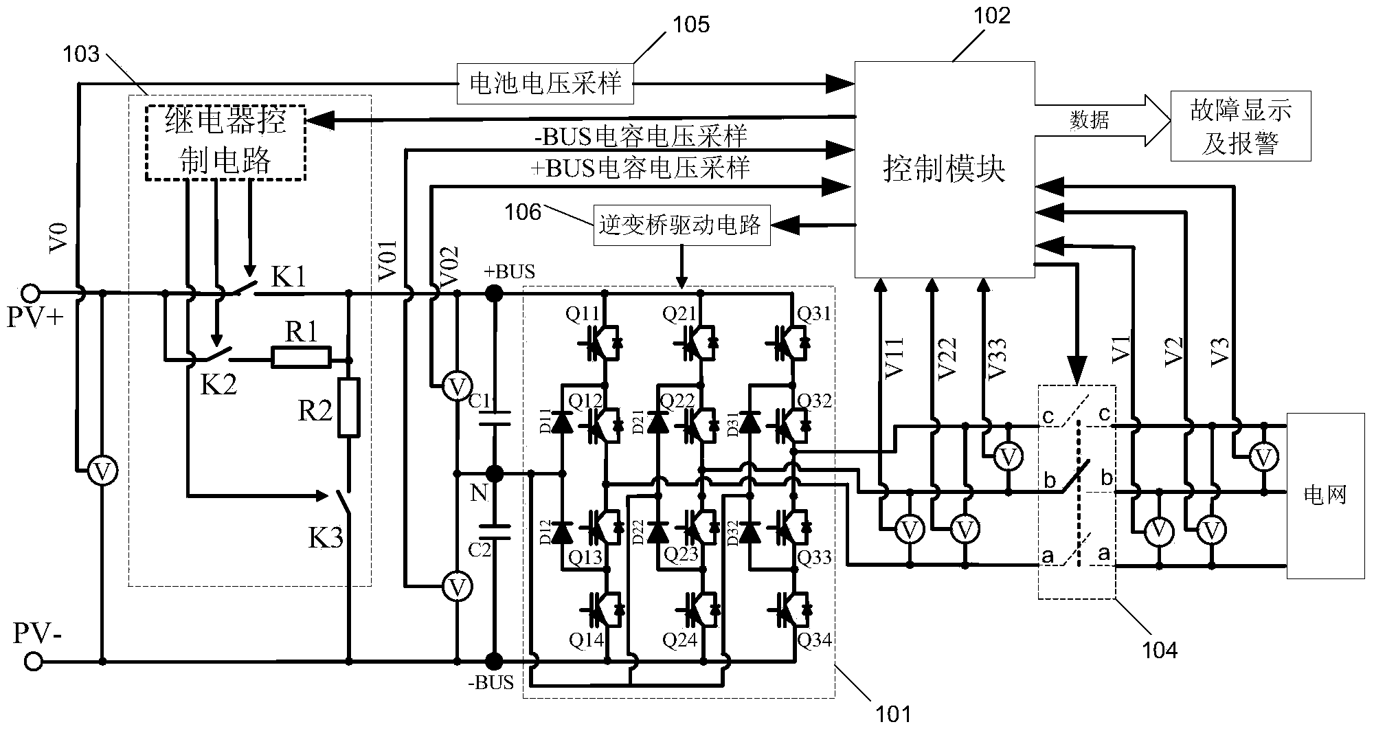
[0027] This embodiment provides a photovoltaic inverter, the first and second input terminals of which are respectively connected to the positive pole and negative pole (PV+ and PV- in the illustration) of a photovoltaic array formed by connecting together a plurality of photovoltaic cells , the output terminal is connected to the grid. Such as figure 1 As shown, the photovoltaic inverter includes an input capacitor branch, an inverter bridge circuit 101 , a control module 102 and a disconnection module connected in sequence. Wherein, the input capacitor branch includes BUS capacitors C1 and C2, which provide energy support for the inverter bridge circuit 101 and are the input voltage for the normal operation of the inverter bridge circuit 101; frequency, same-phase AC current, and feed it to the grid to realize photovoltaic grid-connected power generation; the control module 102 generally uses a single-chip microcomputer or a digital signal processor (DSP) chip as a control ...
Embodiment 2
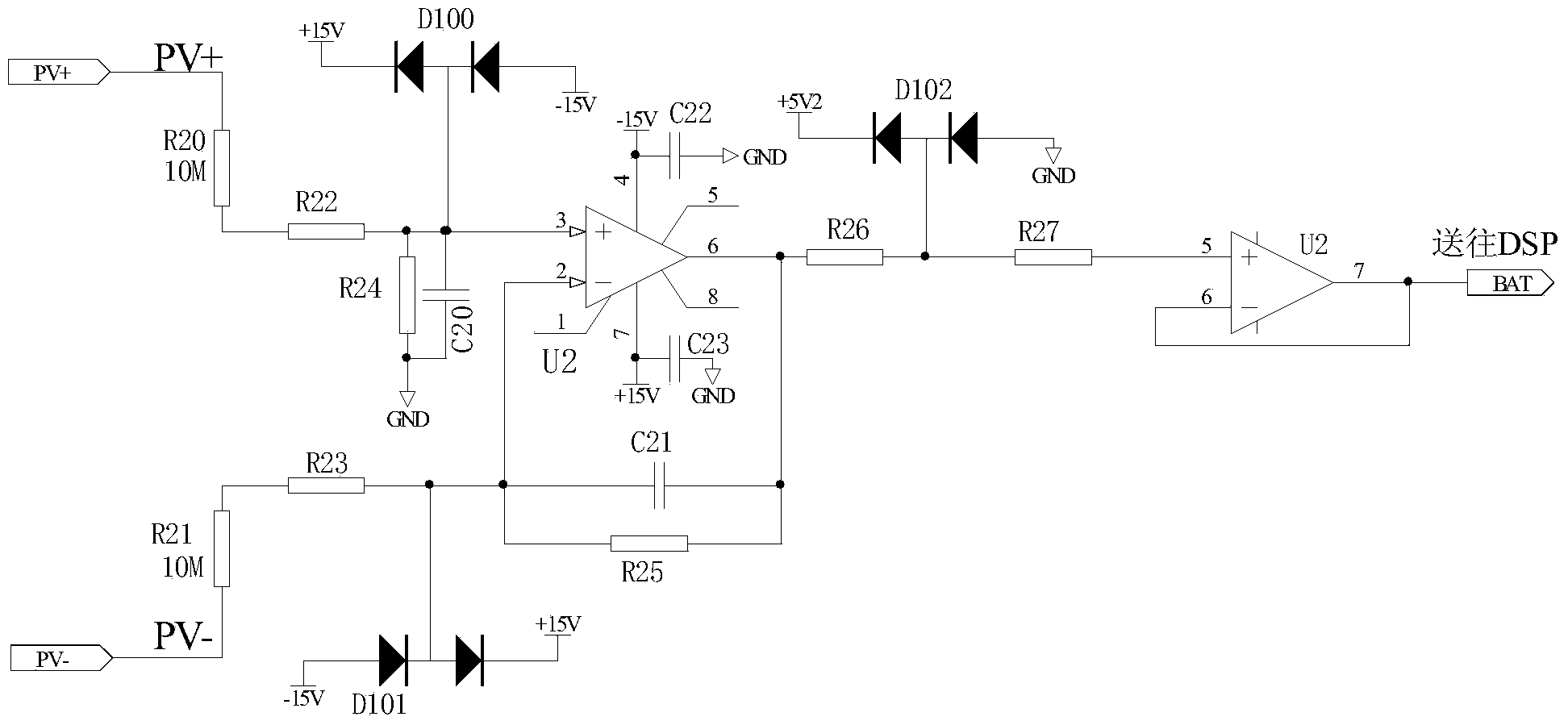
[0038] The photovoltaic inverter provided in this embodiment is the same as that in Embodiment 1, but the difference from Embodiment 1 during power-on self-check is that the voltage of the input capacitor branch obtained by sampling is also judged to determine whether it is equal to the first reference voltage, If it is not equal, it is determined that the inverter bridge of the photovoltaic inverter is faulty, and if it is equal, the power-on self-test is ended. Specifically, through the power-on self-test of Embodiment 1, it is in a low-voltage and low-current state at this time, and then the first reference voltage V can be calculated by the control module 102 in , its calculation formula is
[0039] V in =V pv ×[R 2 ÷(R 1 +R 2 )] (1)
[0040] Among them, V pv Enter the real-time voltage value of the positive and negative terminals for the solar cell voltage.
[0041] The sampling voltage V can be obtained through the voltage samp...
Embodiment 3
[0052] The difference between this embodiment and Embodiment 2 is that, after judging that the voltage of the input capacitor branch obtained by sampling is equal to the first reference voltage, instead of directly ending the power-on self-test, the inverter voltage is detected to determine the voltage of the inverter bridge. Is there a fault. Specifically, the control module 102 sends a pulse width modulation (PWM) signal to invert the inverter bridge, samples the inverter voltage, and judges whether the inverter voltage is equal to the second reference voltage, and if not, determines that the inverter bridge is faulty. If equal, the control module stops sending PWM signals, disconnects the soft-start on-off element K2 and the voltage-dividing on-off element K3, and ends the power-on self-test.
[0053] This embodiment takes three-phase three-wire grid voltage sampling as an example, that is, BC-phase grid voltage V1, CA-phase grid voltage V2, and AB-phase grid voltage V3. V...
PUM
 Abstract
Description
Claims
Application Information
 - R&D
- Intellectual Property
- Life Sciences
- Materials
- Tech Scout
- Unparalleled Data Quality
- Higher Quality Content
- 60% Fewer Hallucinations
Browse by: Latest US Patents, China's latest patents, Technical Efficacy Thesaurus, Application Domain, Technology Topic, Popular Technical Reports.
© 2025 PatSnap. All rights reserved.Legal|Privacy policy|Modern Slavery Act Transparency Statement|Sitemap|About US| Contact US: help@patsnap.com