


Quick Research
Generate reliable direction feasibility study reports for your R&D in just a few steps.

Technical Q&A
Discover and master advanced knowledge NOW. Basics, ideas, possibilities, all at once.

Find Solutions
As an expert in R&D theories, this can generate solutions to your technical problems instantly.

Evaluate Feasibility
Analyze your overall solution with one click, know your potential R&D risks in advance.

Monitor Landscape
Get weekly tech updates, stay abreast of the latest tech innovations and key insights.
Intelligent vacuum cleaner and using method thereof
A smart vacuum cleaner and dust collection technology, applied in vacuum cleaners, applications, household appliances, etc., can solve the problems of high power consumption of motors, non-energy-saving fan features, and increased fan power, so as to achieve the effect of energy saving
- Summary
- Abstract
- Description
- Claims
- Application Information
AI Technical Summary
Problems solved by technology
Method used
Image

Examples
Embodiment 1
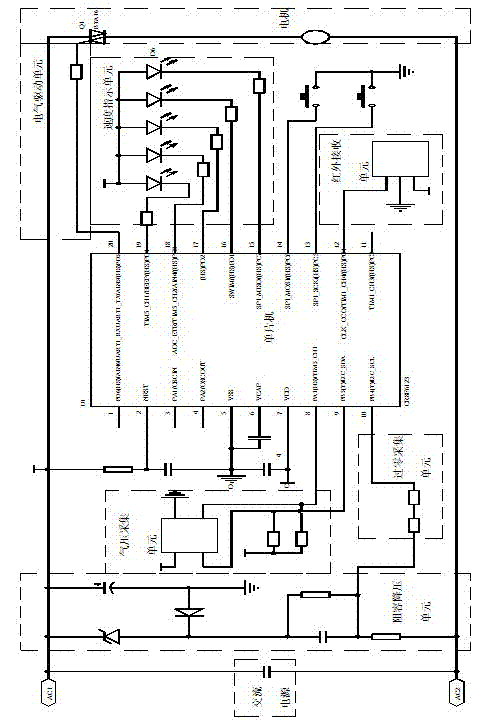
[0024] Such as figure 1 As shown, the smart vacuum cleaner includes a housing, a dust collecting and filtering device and a motor arranged inside the housing, and also includes a control device, and the control device includes:
[0025] Single-chip microcomputer, the input end of the single-chip microcomputer is connected with the following air pressure acquisition unit and zero-crossing acquisition unit, and the output end of the single-chip microcomputer is connected with the following electric drive unit for receiving the air pressure value signal and zero-crossing collected by the air pressure acquisition unit The zero value signal collected by the collection unit is processed and sent to the electric drive unit;
[0026] An air pressure collection unit, connected to the vacuum cleaner cavity, used for collecting the air pressure value signal in the vacuum cleaner cavity and transmitting the air pressure value signal to the single-chip microcomputer;
[0027] The zero-crossing a...
Embodiment 2
[0033] As a preferred embodiment, the rest is the same as Embodiment 1, except that it also includes a speed indicating unit and an infrared receiving unit connected to the single-chip microcomputer.
[0034] In the above embodiment 2, when the motor runs at different speeds, the LED indicator of the speed indicating unit is on, and at the same time, the instruction can be sent to the infrared receiving unit through the external infrared remote controller, and then sent to the single-chip microcomputer, which is more humane.
[0035] A method for using a smart vacuum cleaner includes the following steps:
[0036] Step 1: The motor starts to work, the air pressure sensor collects the air pressure value signal of the vacuum cleaner cavity and transmits the air pressure value signal to the single-chip microcomputer. At the same time, the zero point value signal of the AC power supply is collected and the zero point value signal is transmitted to Single chip microcomputer
[0037] Step 2:...
PUM
 Abstract
Description
Claims
Application Information
 - R&D Engineer
- R&D Manager
- IP Professional
- Industry Leading Data Capabilities
- Powerful AI technology
- Patent DNA Extraction
Browse by: Latest US Patents, China's latest patents, Technical Efficacy Thesaurus, Application Domain, Technology Topic, Popular Technical Reports.
© 2024 PatSnap. All rights reserved.Legal|Privacy policy|Modern Slavery Act Transparency Statement|Sitemap|About US| Contact US: help@patsnap.com