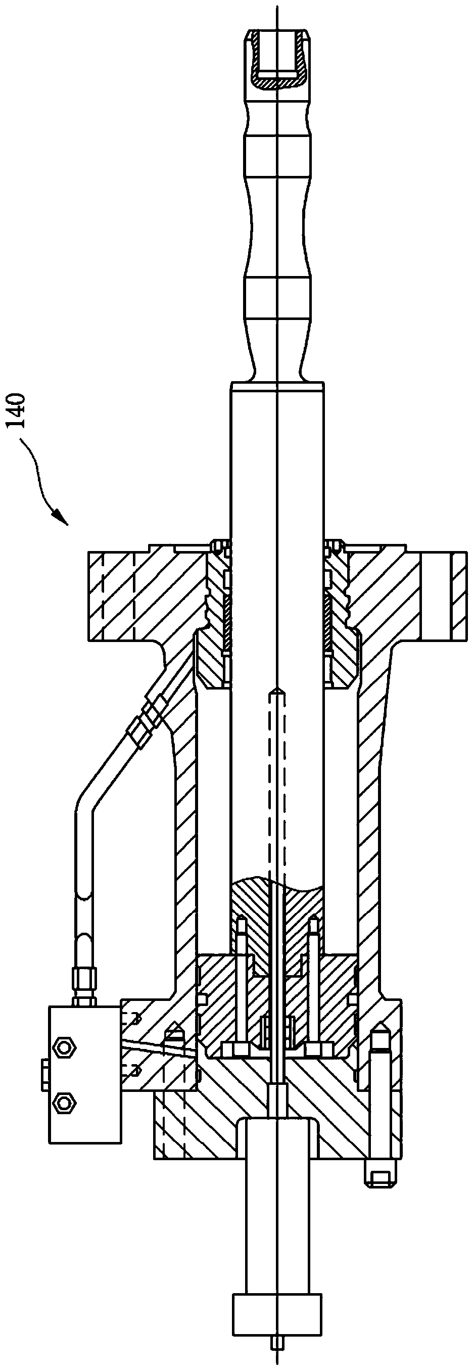
Hydraulic control device using hydraulic actuator

A technology for hydraulic actuators and control devices, which can be used in fluid pressure actuation devices, accumulator devices, fluid pressure actuation system components, etc., and can solve problems such as damage, hydraulic pressure drop, cracks, etc.

Inactive Publication Date: 2014-07-02
SK INNOVATION CO LTD
View PDF6 Cites 5 Cited by
  • Summary
  • Abstract
  • Description
  • Claims
  • Application Information

AI Technical Summary

Problems solved by technology

In typical step control, the capacity of the cylinder is adjusted in steps of 50%-75%-100%, and bypass control is used in the middle range between levels, which results in high energy consumption
In addition, overload is applied to the compressor, causing damage problems such as cracks in welded parts or causing a drop in hydraulic pressure

Method used


Image

  • Hydraulic control device using hydraulic actuator
  • Hydraulic control device using hydraulic actuator
  • Hydraulic control device using hydraulic actuator

Examples


Embodiment Construction

[0036] The various aspects, features and advantages of the present invention will become more apparent from the following detailed description of the preferred embodiments when taken in conjunction with the accompanying drawings. Throughout the drawings, the same reference numerals are used to designate the same or similar parts. If, in the specification, detailed descriptions of known functions or constructions will unnecessarily obscure the gist of the present invention, such detailed descriptions will be omitted.

[0037] Hereinafter, a hydraulic control device using a hydraulic actuator according to an embodiment of the present invention will be described in detail with reference to the accompanying drawings.

[0038] figure 1 is a schematic block diagram showing a hydraulic control device using a hydraulic actuator according to the present invention. Such as figure 1 As shown, the hydraulic control device 100 includes a hydraulic actuator 110, a pressure reducing valve...


PUM


Abstract

The present invention relates to and provides a hydraulic control device using a hydraulic actuator. The device comprises: the hydraulic actuator having a clearance pocket; an oil supply line and an oil discharge line which are respectively connected to said hydraulic actuator; pilot valves which are respectively connected to said oil supply line and said oil discharge line; and an accumulator which additionally supplies oil to said hydraulic actuator, wherein easy hydraulic management can be carried out and pressure can be adjusted and controlled in a more efficient and proper manner.

Description

technical field [0001] The present invention relates to a device capable of controlling the capacity of a hydraulic actuator in a continuously variable control manner using a hydraulic device. Background technique [0002] Generally, hydraulic actuators have a clearance pocket disposed at one end of the cylinder. The clearance chamber is opened and closed by a handle or a pneumatic actuator, so that the volume of the clearance chamber can be changed, thereby making the capacity of the cylinder body controllable. In a typical stepped control, the capacity of the cylinder is adjusted in steps of 50%-75%-100%, and bypass control is used in the middle range between the steps, which results in high energy consumption. In addition, an overload is applied to the compressor, causing damage problems such as cracks in welded parts or causing a drop in hydraulic pressure. To solve this problem, more effective and proper pressure control is required. Contents of the invention [00...

Claims


Application Information

Patent Timeline
Patent Type & Authority Applications(China)
IPC IPC(8): F15B1/027F15B21/08
CPCF15B13/029F15B2211/5059F15B2211/20507F15B2211/7053F15B2211/212F15B2211/20538F15B1/024F15B2211/50554F15B13/043F15B1/027F15B21/08F15B1/04F15B11/10F15B13/021F15B13/024F15B13/025F15B13/0401F15B13/0426F15B2201/00F15B2211/205F15B2211/40576F15B2211/7051
Inventor 金范洙朴东明辛圭彩
Owner SK INNOVATION CO LTD
Why Eureka
Try Eureka