
Cold light integrated curing device and method for optical fiber gyroscope sensitive optical fiber ring

A fiber optic gyroscope and curing device technology, applied in measuring devices, instruments, etc., can solve the problems of uneven curing intensity, low production efficiency, and large production energy consumption of a single bulb irradiating an optical fiber ring, and achieve feasibility and operability performance, improve curing efficiency, and improve efficiency

Active Publication Date: 2014-07-02
中航捷锐(西安)光电技术有限公司
View PDF8 Cites 5 Cited by
  • Summary
  • Abstract
  • Description
  • Claims
  • Application Information

AI Technical Summary

Problems solved by technology

[0003] In the prior art, the method for curing the optical fiber ring is to use a 600W mercury lamp to irradiate the top of the gyroscope for curing. This method has the following disadvantages: 1. The mercury lamp generates huge heat during curing, which increases the thermal stress in the optical fiber ring, and the strain situation Serious; 2. The uneven irradiation of a single bulb makes the curing intensity of the fiber ring uneven, and the power consumption of multiple bulbs is large; 3. It is necessary to change the angle of the mercury lamp to repeatedly irradiate the ring surface and end surface of the fiber ring during curing, resulting in production efficiency. Too low, production energy consumption is too large
[0004] The overall disadvantage of the existing fiber optic ring curing technology is that it brings additional stress to the fiber ring while curing and the efficiency is too low. The low efficiency means that the production of a gyroscope requires manual participation for multiple curing

Method used


Image

  • Cold light integrated curing device and method for optical fiber gyroscope sensitive optical fiber ring
  • Cold light integrated curing device and method for optical fiber gyroscope sensitive optical fiber ring
  • Cold light integrated curing device and method for optical fiber gyroscope sensitive optical fiber ring

Examples


Embodiment Construction

[0030] The structure and working principle of the present invention will be described below in conjunction with the drawings and embodiments, and the examples given are only used to explain the present invention, but not to limit the protection scope of the present invention.

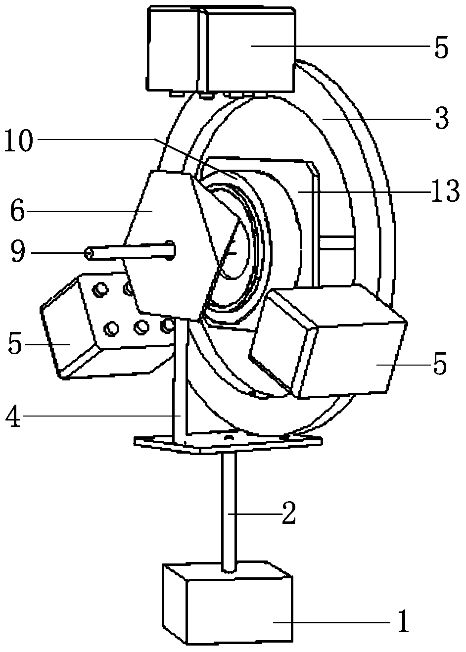
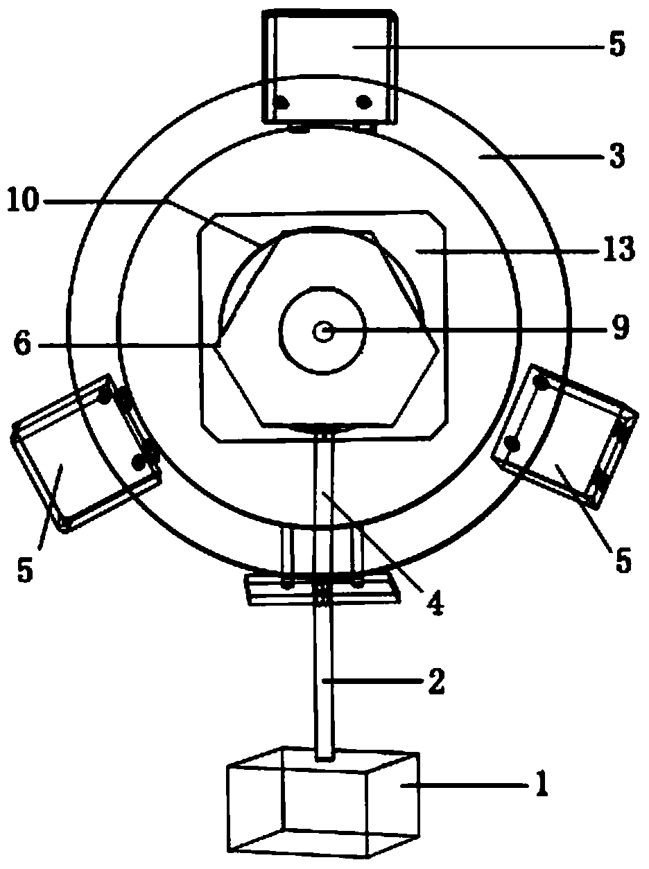
[0031] Such as figure 1 , 2 As shown, the device is generally divided into three parts: a fixed part, a light source part and a rotating shaft control part.

[0032] Wherein, the fixed part includes a stable base 1, on which a support 2 is fixed, the support 2 supports a fixed frame 3 on the one hand, and supports a threaded post 4 with a threaded end on the other hand. . The base 1, the support 2, the fixed frame 3, and the threaded column 4 constitute the fixed part.

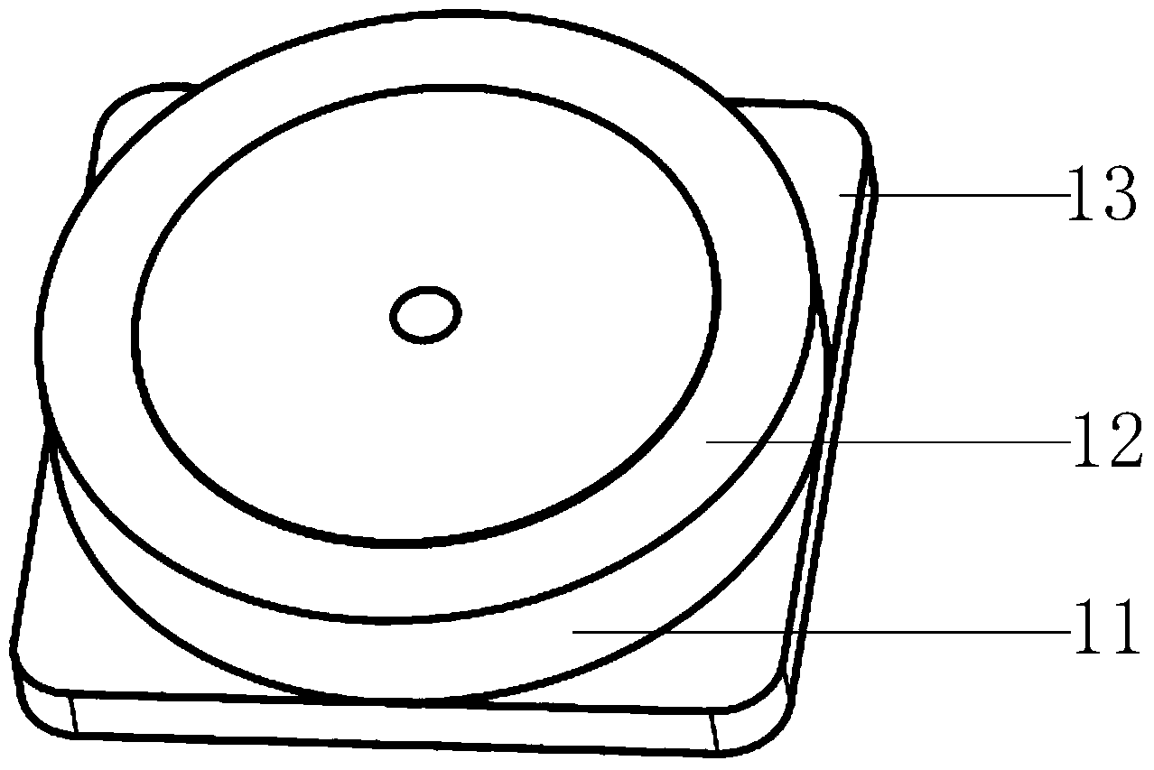
[0033] On the fixed frame 3, several LED ultraviolet lamps 5 are uniformly fixed; a polyhedral reflector 6 is connected to the threaded end of the threaded column 4, and the polyhedral reflector 6 is positioned at the front of the fi...


PUM


Abstract

The invention relates to a cold light integrated curing device and method for an optical fiber gyroscope sensitive optical fiber ring. The device comprises a fixing part, a light source part and a rotating shaft control part, wherein the fixing part is used for fixing a light source; the light source part is used for radiating the optical fiber gyroscope sensitive optical fiber ring to be cured; the rotating shaft control part is used for rotating the optical fiber gyroscope sensitive optical fiber ring to be cured; the light source part comprises an LED (Light Emitting Diode) ultraviolet lamp and a polyhedron reflection mirror. The device is a low-stress integrated curing system, the sensitive optical fiber ring is driven to rotate through a mechanical structure, and the polyhedron mirror in the mechanical structure is utilized to split the ultraviolet light to the end surface and the annular surface of the optical fiber ring, so that the purpose of integrally curing the optical fiber ring is achieved, the stress inside the optical fiber ring is reduced, and the production efficiency of the optical fiber ring is improved.

Description

technical field [0001] The invention relates to the manufacturing technology of the optical fiber gyroscope, in particular to an integrated curing device suitable for the sensitive optical fiber ring of the optical fiber gyroscope, and an integrated curing method using the special curing device. It is suitable for the manufacture of high-precision fiber optic gyroscopes and other fiber optic sensors. Background technique [0002] The sensitive fiber optic ring is the core component of the fiber optic gyroscope. The stability and anti-interference ability of the fiber optic ring directly affect the performance of the fiber optic gyroscope. Therefore, in the development process of the fiber optic gyroscope, the manufacturing technology of the fiber optic ring is one of the key technologies. Optical fiber ring curing refers to the process of curing the optical fiber ring by changing the adhesive for bonding the optical fiber from liquid to solid under certain conditions. This c...

Claims


Application Information

Patent Timeline
Patent Type & Authority Applications(China)
IPC IPC(8): G01C25/00
CPCG01C25/00
Inventor 谢良平霍雷崔志超杨东锟李彬王媛娣
Owner 中航捷锐(西安)光电技术有限公司
Learn More