Layered honeycomb ceramic

A honeycomb ceramic and layered technology, which is applied in the field of organic waste gas treatment devices, can solve the problems that the air flow cannot be redistributed, the device cannot operate normally, and the thermal shock resistance is not good, so as to solve the problem of frequent parking and cleaning. Conducive to the release of thermal stress and the effect of improving thermal shock resistance

Inactive Publication Date: 2014-07-02
FUJIAN JUNGIE NEW MATERIAL TECH CO LTD
View PDF6 Cites 4 Cited by
  • Summary
  • Abstract
  • Description
  • Claims
  • Application Information

AI Technical Summary

Problems solved by technology

The characteristic of this kind of honeycomb ceramic is that it has a large specific surface area. The disadvantage is that the internal holes (slots) and holes (slots) of the product are independent straight channels, and the channel length of the holes runs through the entire height of the device. Lateral redistribution cannot be carried out in the exhaust gas, which brings the following problems: First, because the exhaust gas usually contains certain impurities (such as sand and dust and other solid particles), these impurities can easily cause blockage of the pore channels if they accumulate for a long time. As a result, the device cannot operate normally and must be stopped for cleaning in stages; secondly, when the exhaust gas entering the RTO device is unevenly distributed, the air flow in the device cannot be redistributed, resulting in increased resistance of the system and reduced thermal efficiency; Third, the channel of the hole is long, which is not conducive to heat transfer; fourth, the height of the product is large, which is not conducive to the release of thermal stress, and the product has poor thermal shock resistance

Method used


Image

  • Layered honeycomb ceramic
  • Layered honeycomb ceramic
  • Layered honeycomb ceramic

Examples


Embodiment Construction

[0023] In order to describe the technical content, structural features, achieved goals and effects of the present invention in detail, the following will be described in detail in conjunction with the embodiments and accompanying drawings.

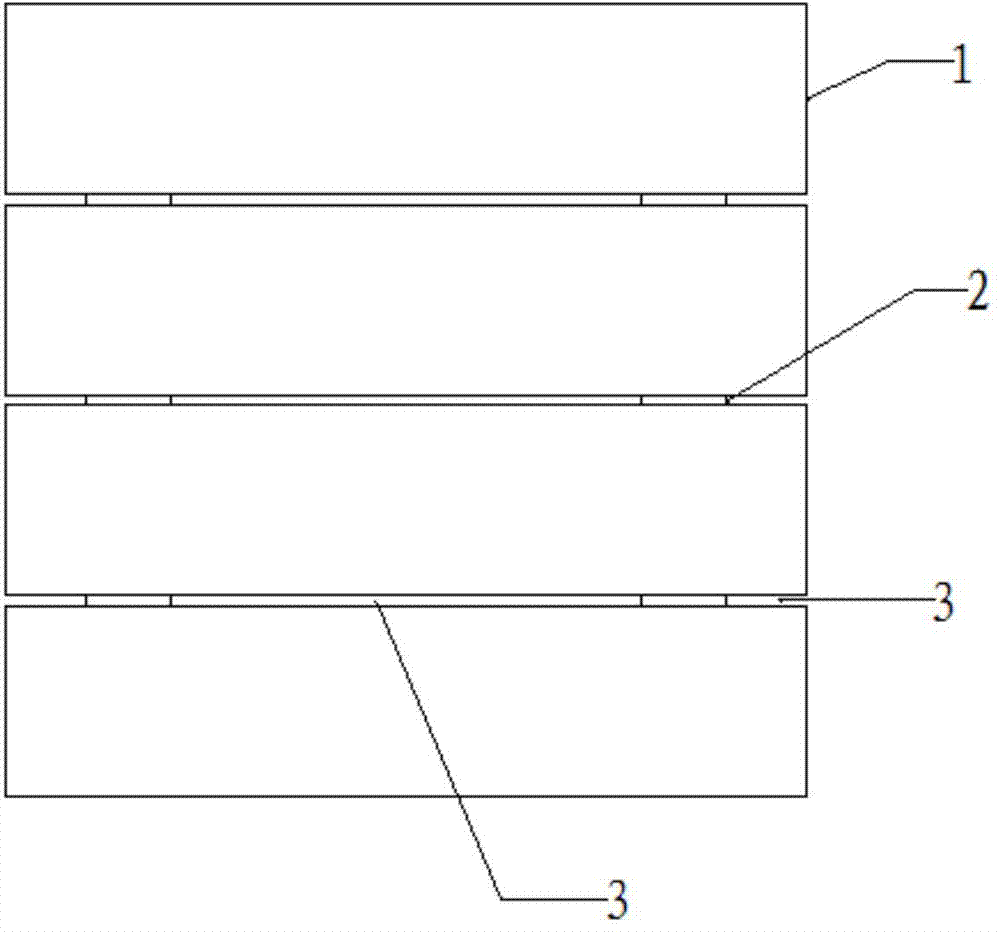
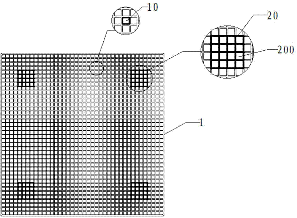
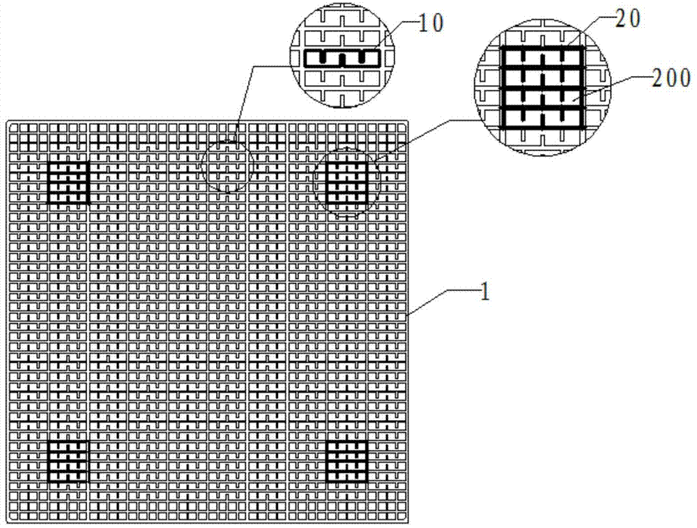
[0024] see Figure 1 to Figure 3 As shown, the layered honeycomb ceramics of this embodiment is formed by stacking more than two layers of structural units 1 and more than one layer of gasket layers 2 arranged between adjacent two layers of structural units 1 along the longitudinal direction. The structural unit 1 is distributed in a network shape with more than one gas channel A10 longitudinally penetrating the structural unit 1, the gas channels A10 on the same structural unit 1 are not connected to each other, and the gas channels A10 of the adjacent two-layer structural unit 1 One-to-one correspondence, the gasket layer 2 is composed of more than one gasket 20 distributed on this level at intervals, and the gas channels A10 of the adja...


PUM

PropertyMeasurementUnit
heightaaaaaaaaaa
heightaaaaaaaaaa

Abstract

The invention relates to layered honeycomb ceramic. The layered honeycomb ceramic is formed by longitudinal stacking of more than two layers of structural units and more than one spacer layer arranged between every two adjacent layers of structural units, more than one gas channel A penetrating through each structural unit is distributed in each structural unit in a meshed manner, the gas channels A on the same structural unit are unconnected mutually, the gas channels A of every two adjacent layers of structural units are in one-to-one correspondence, each spacer layer is composed of more than one spacer distributed on the layer surface in a spacing manner, and the gas channels A of the every two adjacent layers of structural units located outside a spacer region are mutually connected through gaps between the spacers as well as between the spacers and the edges of the structural units. Gas distribution in the honeycomb ceramic is improved, system resistance of an RTO device is reduced beneficially, and heat efficiency is improved.

Description

technical field [0001] The invention relates to the technical field of organic waste gas treatment devices, in particular to a layered honeycomb ceramic. Background technique [0002] Honeycomb ceramics is a key component of the organic waste gas treatment device - Regenerative Thermal Oxidation Reactor (RTO). Its main function is to store heat and release heat, that is, to store the heat of the organic waste gas burned in the RTO device in the honeycomb ceramics. And transfer the stored heat to the cold waste gas to be treated, so as to increase the temperature of the waste gas and save the heat required for waste gas treatment. [0003] Existing honeycomb ceramics, its structure is a one-time extruded rectangular parallelepiped, the height of the rectangular parallelepiped is generally 150mm, 300mm or more, the cross section is square, and the hole structure is a straight-through square hole independent of each other or a partially connected groove shape. holes (slotted h...

Claims


Application Information

Patent Timeline
Patent Type & Authority Applications(China)
IPC IPC(8): F28D20/00F23G7/06
CPCY02E60/142Y02E60/14
Inventor 吴文忠李洪发黄茂金李锦新
Owner FUJIAN JUNGIE NEW MATERIAL TECH CO LTD
Why Eureka
Try Eureka