
Half-grouting sleeve embedded with cone

A semi-grouting sleeve and cone-shaped technology, applied in structural elements, building components, building reinforcements, etc., can solve the problems of bulky sleeve shape, time-consuming and labor-intensive processing, time-consuming and labor-intensive, etc., so as to reduce material costs and widen engineering applications. Foreground, processing and making simple effects

Active Publication Date: 2014-07-02
SOUTHEAST UNIV
View PDF10 Cites 16 Cited by
  • Summary
  • Abstract
  • Description
  • Claims
  • Application Information

AI Technical Summary

Problems solved by technology

[0009] The semi-grouting sleeve disclosed in Chinese patent document CN102587586A has the above-mentioned advantages, but still has the following problems: ① the grooves and / or ribs are formed by casting or machining, and the disadvantages of time-consuming and labor-intensive processing have not been fundamentally resolved; ②The grooves and / or convex ribs are made by rolling or spinning, and rely on multiple grooves inside the sleeve to resist shearing. Requirements, the wall thickness of the sleeve is relatively large, so as to ensure that the tensile force at the thinnest position of the sleeve wall after rolling (pressing) is greater than the tensile force of the connecting steel bar, which will directly lead to the bulky shape of the sleeve; on the other hand, Machining multiple grooves and / or ribs is still time-consuming and labor-intensive
[0010] In summary, the existing semi-grouting sleeves have disadvantages such as difficult processing, bulky form, and high cost, which is not conducive to the current development of my country's housing industrialization and construction industrialization

Method used


Image

  • Half-grouting sleeve embedded with cone
  • Half-grouting sleeve embedded with cone

Examples


Embodiment 1

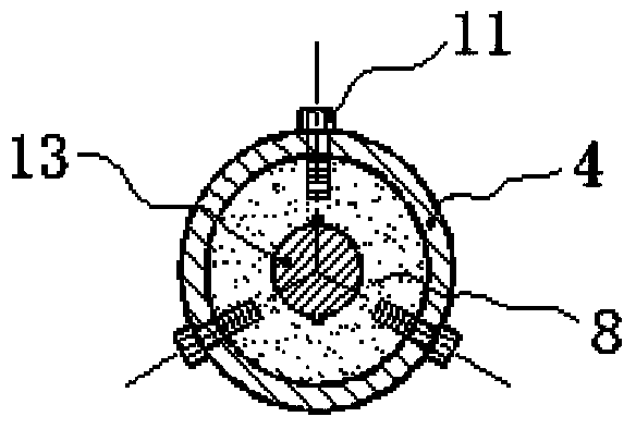
[0028] A semi-grouting sleeve embedded with a cone in the present invention, comprising: a connector 3, a sleeve body 4, a grouting opening 6, a grouting opening 7, a cone 9, a welding seam 10, a shear bolt 11, an elastic Rubber sealing ring 12. The connector 3 is provided with a connector internal thread 31 and a connector groove 32; the sleeve body 4 is embedded with a cone 9; the cone 9 is welded to the sleeve body 4 The slit 10 is fixed; the sleeve body 4 is provided with 3 rows of screw holes, the screw holes are provided with threads, the position interval of the 3 rows of screw holes is 120 degrees, and the screw holes are screwed with shear bolts 11; The sleeve body 4 is processed from high-quality carbon structural steel, low-alloy high-strength steel, and alloy structural steel

[0029] After the connecting piece is put into the sleeve body, the sleeve body is rolled to reduce the inner diameter corresponding to the concave part of the connecting piece, and the end ...


PUM


Abstract

The invention discloses a half-grouting sleeve embedded with a cone. The half-grouting sleeve comprises a connecting piece (3), a sleeve body (4), a grouting port (6), a grout outlet (7), a cone (9), a shearing bolt (11) and an elastic rubber sealing ring (12), wherein the connecting piece (3) is arranged at one end in the sleeve body (4), and the elastic rubber sealing ring (12) is arranged at the other end of the sleeve body (4); the cone (9) is embedded at one end, which is provided with the elastic rubber sealing ring (12), of the sleeve body (4); the grouting port (6) and the grout outlet (7) are formed in an outer wall on the side face of the sleeve body (4); the shearing bolt (11) is arranged on a middle part of the sleeve body (4); one end of a fixing side thread steel bar (1) is connected with the connecting piece (3); one end of an insertion side thread steel bar (13) penetrates through the elastic rubber sealing ring (12); the cone (9) is positioned in the sleeve body (4). The half-grouting sleeve has the advantages of simplicity in manufacturing, low cost and the like, is particularly applied to connection of longitudinal steel bars of beams, posts and shear wall members, can be widely applied to an assembled concrete structure and has wide engineering application prospects.

Description

technical field [0001] The invention relates to a grout-anchored sleeve connector used for connecting steel bars between prefabricated concrete components, belonging to the technical field of construction engineering, in particular to a semi-grouted sleeve embedded with a cone. Background technique [0002] As we all know, prefabricated concrete structure is a structural form that conforms to industrial production methods. It has the advantages of fast construction speed, low labor intensity, less noise pollution and wet work, and easy control of product quality. It is the development direction of my country's future construction. [0003] The core and difficulty of prefabricated concrete structures is the connection of steel bars. The common forms of steel bar connection include mechanical connection, welding connection, lap connection, etc., but there is a problem that concrete needs to be poured at the connection node after the connection. The cement grouting sleeve conne...

Claims


Application Information

Patent Timeline
IPC IPC(8): E04C5/18
Inventor 潘金龙单奇峰
Owner SOUTHEAST UNIV
Learn More