Thin steel ring processing method
A processing method and thin steel technology, applied in the field of mechanical processing, can solve the problems such as the inability to guarantee the flatness requirements, and achieve the effect of ensuring the flatness requirements
- Summary
- Abstract
- Description
- Claims
- Application Information
AI Technical Summary
Problems solved by technology
Method used
Image
Examples
Embodiment 1
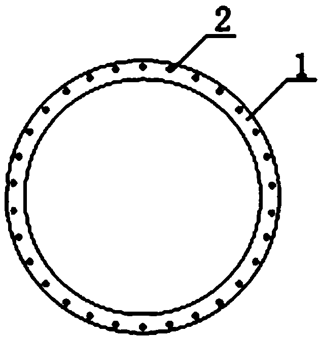
[0028] The thin steel ring 1 used by a certain type of helicopter has 12 through holes 2 with a diameter of 8.5mm evenly distributed along the circumference. The thickness of the thin steel ring 1 is t=2mm, and the outer diameter of the thin steel ring 1 is D=300mm. The radial width of 1 is s=25mm; the processing steps are as follows:
[0029] 1. Cutting: use CNC milling machine to cut a round wool, the thickness of the wool is t1=7mm, and the outer diameter of the wool is D1=340mm;
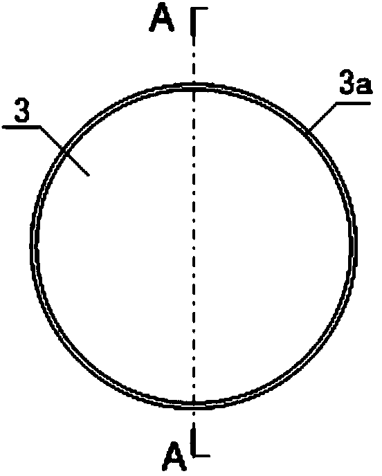
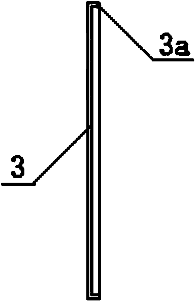
[0030] 2. Rough machining: CNC milling machine is used, the pressure plate is pressed on the edge of the wool, and a circular groove is milled on the upper surface of the circular wool to form the first blank. The bottom of the circular groove forms the web 3, and the inner diameter of the web 3 is D1=315mm. The thickness of the web 3 is t, and the groove wall of the circular groove forms an annular skirt 3a;
[0031] 3. Drilling: Using a CNC machine tool, drill 12 through holes 2 of 8.5mm along...
Embodiment 2
[0038] The thin steel ring 1 used by a certain type of helicopter has 20 through holes 2 with a diameter of 8.5mm evenly distributed along the circumference, the thickness of the thin steel ring 1 is t=3mm, and the outer diameter of the thin steel ring 1 is D=400mm. The radial width of 1 is s=30mm; the processing steps are as follows:
[0039] 1. Cutting: use CNC milling machine to cut a round wool, the thickness of the wool is t1=10mm, and the outer diameter of the wool is D1=460mm;
[0040] 2. Rough machining: Using a CNC milling machine, the pressure plate is pressed on the edge of the wool, and a circular groove is milled on the upper surface of the circular wool to form the first blank. The bottom of the circular groove forms the web 3, and the inner diameter of the web 3 is D1=418mm. The thickness of the web 3 is t, and the groove wall of the circular groove forms an annular skirt 3a;
[0041] 3. Drilling: Using a CNC machine tool, drill 20 through holes 2 of 8.5mm alon...
Embodiment 3
[0048] The thin steel ring 1 used by a certain type of helicopter has 30 through holes 2 with a diameter of 8.5mm uniformly distributed along the circumference, the thickness of the thin steel ring 1 is t=4mm, and the outer diameter of the thin steel ring 1 is D=500mm. The radial width of 1 is s=50mm; the processing steps are as follows:
[0049] 1. Cutting: use CNC milling machine to cut a round wool, the thickness of the wool is t1=20mm, and the outer diameter of the wool is D1=560mm;
[0050] 2. Rough machining: CNC milling machine is used, the pressure plate is pressed on the edge of the wool, and a circular groove is milled on the upper surface of the circular wool to form the first blank. The bottom of the circular groove forms the web 3, and the inner diameter of the web 3 D1=520mm, The thickness of the web 3 is t, and the groove wall of the circular groove forms an annular skirt 3a;
[0051] 3. Drilling: Using a CNC machine tool, drill 30 through holes 2 of 8.5mm alon...
PUM
| Property | Measurement | Unit |
|---|---|---|
| thickness | aaaaa | aaaaa |
| width | aaaaa | aaaaa |
| thickness | aaaaa | aaaaa |
Abstract
Description
Claims
Application Information
 - R&D Engineer
- R&D Manager
- IP Professional
- Industry Leading Data Capabilities
- Powerful AI technology
- Patent DNA Extraction
Browse by: Latest US Patents, China's latest patents, Technical Efficacy Thesaurus, Application Domain, Technology Topic, Popular Technical Reports.
© 2024 PatSnap. All rights reserved.Legal|Privacy policy|Modern Slavery Act Transparency Statement|Sitemap|About US| Contact US: help@patsnap.com


