Equipment installation base with convenience for leveling

A technology for equipment installation and installation grooves, applied in the direction of mechanical equipment, engine frame, special foundation layout, etc., can solve the problems of poor accuracy of construction equipment, inconvenient adjustment, and uneven quality of construction personnel, so as to facilitate adjustment and tightening operations. , The leveling effect is good, and the effect of ensuring the flatness

Active Publication Date: 2012-08-01
CCCC SHANGHAI THIRD HARBOR SCI RES INST CO LTD +1
View PDF4 Cites 1 Cited by
  • Summary
  • Abstract
  • Description
  • Claims
  • Application Information

AI Technical Summary

Problems solved by technology

At present, the simplest installation base of the reaction force frame is a pre-embedded steel plate, but this method of pre-embedded steel plates often suffers from uneven shrinkage of concrete, poor construction equipment precision, and uneven quality of construction personnel during construction. , so that the flatness of the pre-embedded steel plate is difficult to meet the requirements, it is necessary to install a leveling base to meet the requirements of the equipment for the flatness of the installation plane
In this way, not only the structure of the installation base becomes complicated, but also the adjustment is not convenient enough.

Method used


Image

  • Equipment installation base with convenience for leveling
  • Equipment installation base with convenience for leveling
  • Equipment installation base with convenience for leveling

Examples


Embodiment Construction

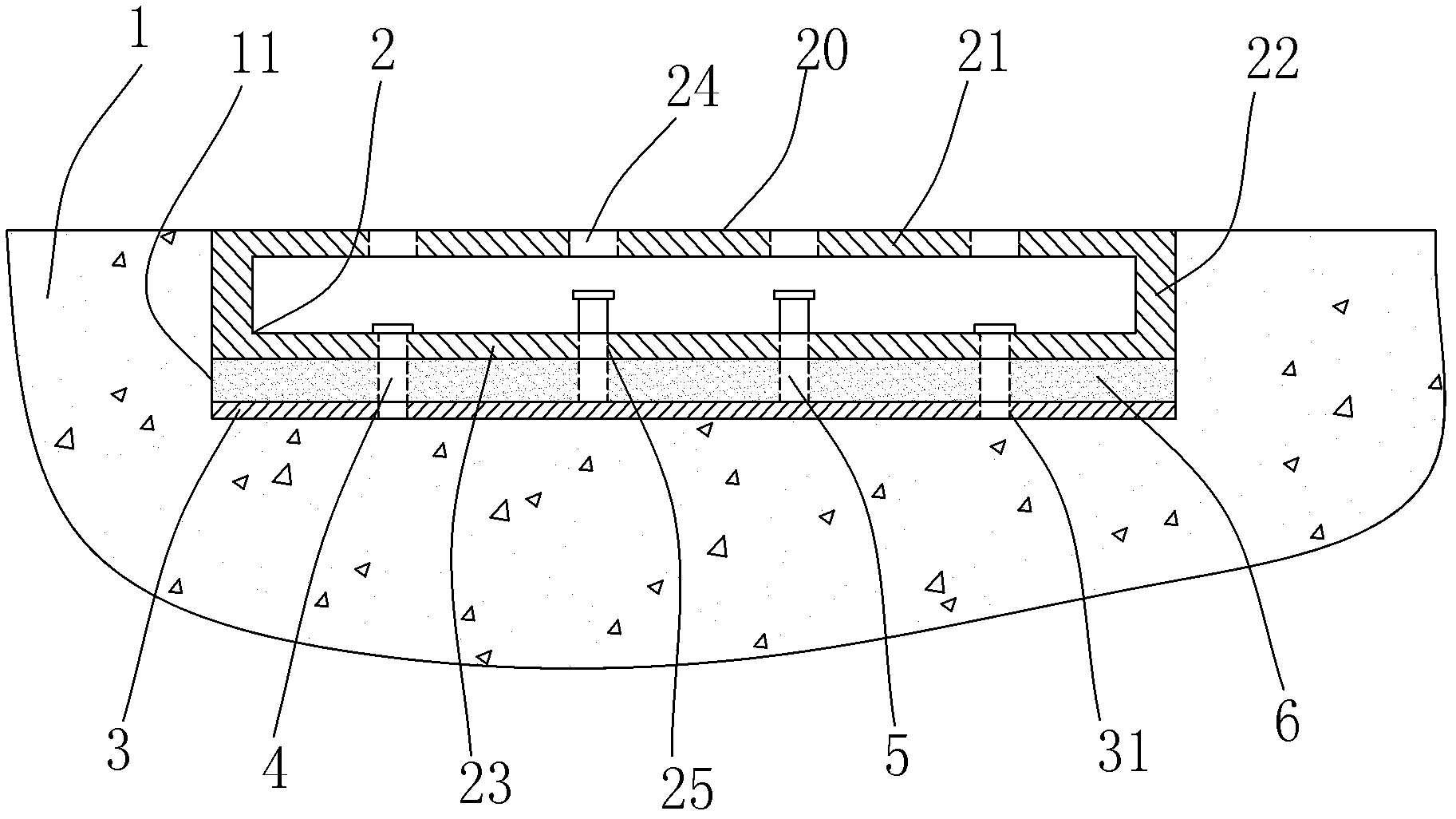
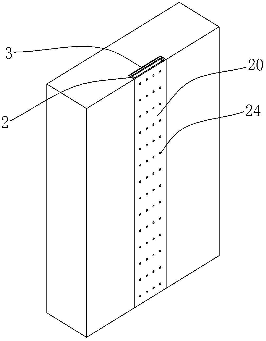
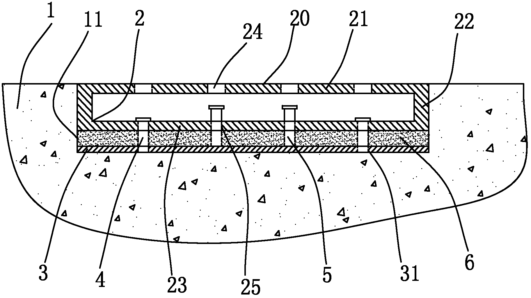
[0015] Such as figure 1 As shown, the equipment installation base for easy leveling of the present invention includes a concrete wall 1, and the concrete wall 1 is provided with an installation groove 11. A substrate steel plate 3 is embedded in the bottom of the installation groove 11, and a steel plate 3 can be accommodated in the installation groove 11. The box girder 2, the box girder 2 is surrounded by an upper plate 21, a lower plate 23 and two side plates 22 to form a box shape, and the lower plate 23 is located above the substrate steel plate and parallel to the substrate steel plate 3.

[0016] The lower plate 23 is provided with a plurality of screw holes 25, and a plurality of adjusting screws 5 and a plurality of fastening screws 4 are respectively installed in these screw holes 25, wherein the lower ends of the adjusting screws 5 pass through the screw holes 25 and push against the substrate steel plate 3, the lower end of the fastening screw 4 passes through the ...


PUM


Abstract

The invention discloses an equipment installation base with convenience for leveling. The equipment installation base comprises a concrete wall and an installation plane, wherein an installation groove is arranged on the concrete wall; a substrate steel plate is pre-buried at the bottom of the installation groove; the installation groove is further internally provided with a box beam; the box shape of the box beam is enclosed by an upper flat plate, a lower flat plate and two side plates; the lower flat plate is opposite to the substrate steel plate in parallel; a plurality of screw holes are formed in the lower flat plate; a plurality of adjusting screws and a plurality of fastening screws are arranged in the screw holes; the lower ends of the adjusting screws are butted against on the upper surface of the substrate steel plate after penetrating through the screw holes; the lower ends of the fastening screws are fixedly connected with the substrate steel plate after penetrating through the screw holes; operating through holes corresponding to the screw holes are formed in the upper flat plate; and the installation plane is positioned on the upper flat plate. The equipment installation base disclosed by the invention has a good leveling effect, can achieve flatness requirements even for the base with a larger installation plane, and is very convenient to use.

Description

technical field [0001] The invention relates to an installation base structure of equipment, in particular to an installation base structure requiring the flatness of the installation plane. Background technique [0002] In the field of civil engineering, mechanical engineering or laboratory, in order to install large equipment, it is necessary to equip the equipment with a mounting base. [0003] For example, large-scale loading equipment is generally equipped in civil structure laboratories, and these equipment are often equipped with large-scale reaction frames, which generally have extremely high requirements on the flatness of the base. At present, the simplest installation base of the reaction force frame is a pre-embedded steel plate, but this method of pre-embedded steel plates often suffers from uneven shrinkage of concrete, poor construction equipment precision, and uneven quality of construction personnel during construction. , so that the flatness of the pre-emb...

Claims


Application Information

Patent Timeline
Patent Type & Authority Applications(China)
IPC IPC(8): F16M7/00F16M9/00
Inventor 吴锋周国然邱松傅一帆
Owner CCCC SHANGHAI THIRD HARBOR SCI RES INST CO LTD
Why Eureka
Try Eureka