
Casting Method of Steel Castings for Traction Center of Metro Vehicles

A technology of vehicle traction and steel castings, which is applied to casting molding equipment, casting molds, casting mold components, etc., can solve the problems of not allowing welding repairs, low casting yield, complex stress conditions, etc., and achieve good feeding , Guarantee the quality of castings and the effect of compact structure

Active Publication Date: 2016-09-14
CRRC QISHUYAN INSTITUTE CO LTD +1
View PDF5 Cites 0 Cited by
  • Summary
  • Abstract
  • Description
  • Claims
  • Application Information

AI Technical Summary

Problems solved by technology

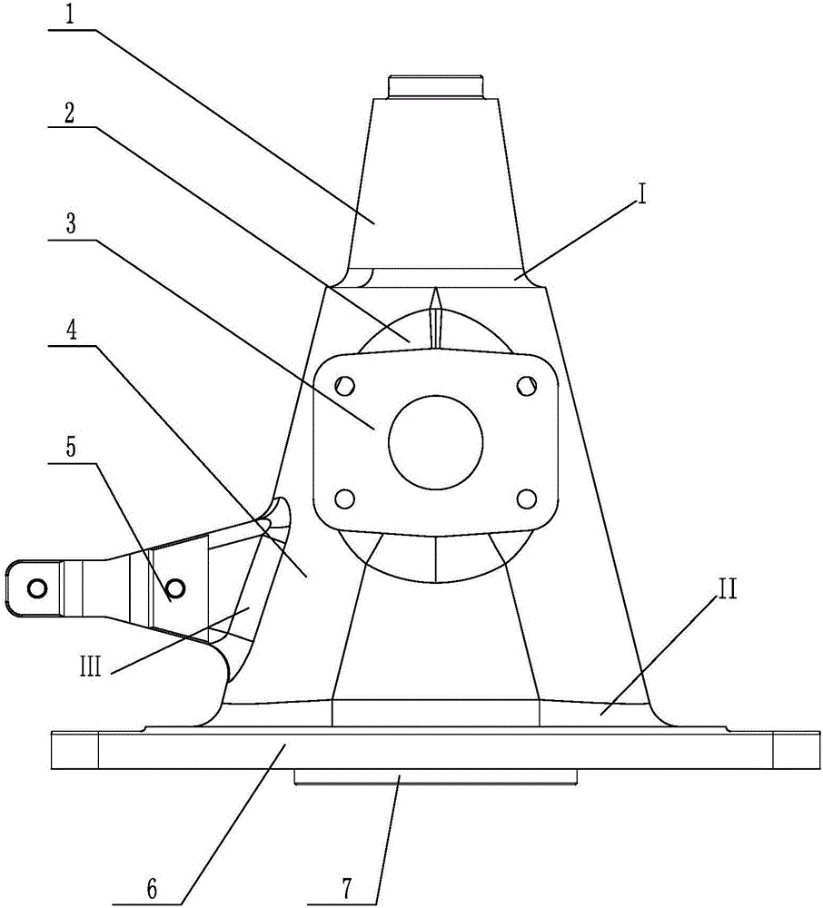
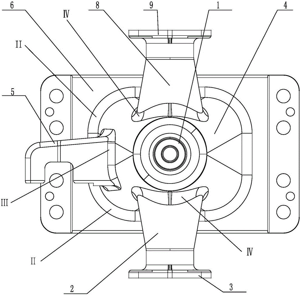
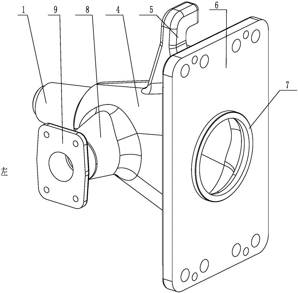
Furthermore, in the actual working environment of the traction center, the stress situation is more complicated, especially the connection and handover part III between the connecting rod connecting seat 5 of the traction center and the main cylinder body 4, the connection part I between the taper part and the main cylinder body, and the large flange 6 The transfer part II connecting the main body cylinder 4 and the left small flange body 8, and the transfer point IV between the right small flange body and the main body body 4 are subject to torsion during operation, so these parts are not allowed to be welded and repaired. It means that these parts are not allowed to have original casting defects exceeding the standard
However, the traction center steel casting produced by the existing casting process is prone to crack defects in these parts, resulting in low casting yield

Method used


Image

  • Casting Method of Steel Castings for Traction Center of Metro Vehicles
  • Casting Method of Steel Castings for Traction Center of Metro Vehicles
  • Casting Method of Steel Castings for Traction Center of Metro Vehicles

Examples


Embodiment Construction

[0024] See Figure 3-5 As shown, the casting method of the subway vehicle traction center steel casting of the present invention includes making metal aluminum molds, core making, molding, box closing, charge smelting, pouring, cooling, casting cleaning, heat treatment, and flaw detection.

[0025] (1) The present invention uses the end face of the large flange plate 6 of the casting and the central section of the taper part 1 as the upper and lower parting surfaces to make a metal aluminum mold; the internal cavity symmetry plane of the casting is used as the upper and lower parting surfaces of the core block to make the metal aluminum mold The core block box, the core block box of the present invention is a half-half structure.

[0026] (2) Make upper type, lower type and core block with ester hardened water glass quartz sand, remove the mold after self-hardening, and brush the alcohol-based zircon powder coating on the surface. The core block of the present invention includ...


PUM

PropertyMeasurementUnit
tensile strengthaaaaaaaaaa

Abstract

The invention relates to a casting method for a metro vehicle traction center steel casting. The method comprises the following steps: (1) manufacturing a metallic aluminium mold by taking one end surface of a large flange plate of a casting and the central section of a tapper part of the casting as upper and lower parting surfaces; and manufacturing a core block box of the metallic aluminium mold by taking symmetrical surfaces of an inner cavity of the casting as upper and lower parting surfaces; (2) manufacturing an upper casting, a lower casting and a core block by using ester hardening water glass silica sand, and drawing after self-hardening; (3) arranging lower external chill, heat preservation dead heads, heating dead heads and auxiliaries on the corresponding parts of the lower casting, arranging upper external chill on the corresponding parts of the upper casting, introducing a pouring system into the parting surfaces from the tapper part; (4) performing surface drying on the upper casting, the lower casting and the core block; and putting the core block in the lower casting and performing mould assembling; and (5) smelting molten steel, and pouring the casting; (6) cooling, performing mould disassembling, and performing shakeout, cleaning the casting, grinding, and repairing welding. The casting manufactured by adopting the method has the characteristics that the structure is compact, the mechanical property can meet the requirement, the rate of casting finished products is high.

Description

technical field [0001] The invention relates to a casting method for a steel casting of a traction center of a subway vehicle, belonging to the technical field of casting. Background technique [0002] The traction center is a part of the subway vehicle bogie, which connects the bogie frame and the bolster, and is the key component for the running part of the subway vehicle to realize the steering. As a connecting component in the bogie system, the traction center bears forces in various directions during the operation of the subway vehicle. Under such operating conditions, the quality of the castings of the traction center must be fully guaranteed. See Figure 1-3 As shown, the traction center has a main body cylinder 4 and a large flange 6 located on one side of the main body cylinder 4. There is a taper part 1 at the other end of the main body cylinder 4, and symmetrical flanges are arranged along the central axis of the main body cylinder 4. The left small flange cylind...

Claims


Application Information

Patent Timeline
Patent Type & Authority Patents(China)
IPC IPC(8): B22C9/22B22C9/08B22C9/10C21D9/00
Inventor 曹松肖恭林潘连明邹寅张大伟詹璐瑶赖凌远
Owner CRRC QISHUYAN INSTITUTE CO LTD
Learn More