Reflection type time-of-flight mass spectrometer with quality filtering function, and use method thereof

A time-of-flight mass spectrometry and reflective technology, which is applied in the field of reflective time-of-flight mass spectrometers, can solve problems affecting weak signal detection, high background noise, and large differences in ion signals, so as to improve detection sensitivity, reduce background noise, increase The effect of large dynamic range

Inactive Publication Date: 2014-06-18
DALIAN INST OF CHEM PHYSICS CHINESE ACAD OF SCI
View PDF6 Cites 16 Cited by
  • Summary
  • Abstract
  • Description
  • Claims
  • Application Information

AI Technical Summary

Problems solved by technology

However, in practical applications, on the one hand, the samples to be analyzed are usually relatively complex, and the contents of different components often have several orders of magnitude differences, which will cause large differences in the ion signals of different components; on the other hand, when flying When the time-based mass spectrometer uses electron bombardment ionization sources, glow discharge ionization sources, chemical ionization sources, etc. as ion sources, it will generate very strong ion signals of background molecules or ion signals of reaction reagents.
Because traditional time-of-flight mass spectrometers do not have the mass filtering function of quadrupole mass spectrometers and ion trap mass spectrometers, in these two cases, strong ion signals will not only saturate the MCP (MicroChannelPlate) ion detector, but also affect weak signals Therefore, there will be measurement errors for both strong and weak signals, which will reduce the dynamic range of the instrument, and will also generate high background noise, which will reduce the detection sensitivity of the instrument.

Method used


Image

  • Reflection type time-of-flight mass spectrometer with quality filtering function, and use method thereof

Examples


Embodiment Construction

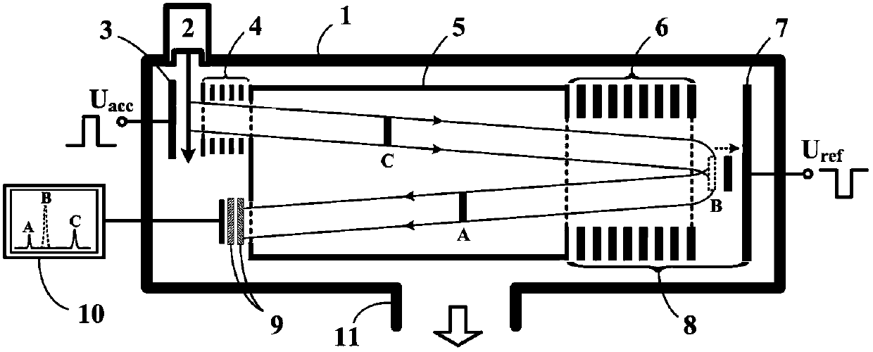
[0033] see figure 1 , is a schematic diagram of the structure and working principle of the present invention. The time-of-flight mass spectrometer of the present invention includes an ion reflection electrode 7 , and a pulse voltage is applied to the ion reflection electrode 7 .

[0034] Including vacuum cavity 1, ion source 2, ion extraction electrode 3, acceleration zone 4, field-free flight zone 5, reflector 8 and MCP ion detector 9;

[0035] The coaxial ion deceleration electrode 6 and the plate-shaped ion reflection electrode 7 constitute a reflector 8;

[0036] The ion extraction electrode 3, the acceleration area 4, the field-free flight area 5, the ion deceleration electrode 6, and the ion reflection electrode 7 are sequentially arranged inside the vacuum chamber 1; the MCP ion detector 9 is arranged inside the vacuum chamber 1, and It is on the same side of the field-free flight zone 5 as the acceleration zone 4;

[0037] The ion extraction electrode 3 is a plate s...


PUM


Abstract

The invention relates to a reflection type time-of-flight mass spectrometer with a quality filtering function. The reflection type time-of-flight mass spectrometer comprises an ion reflection electrode which a pulse voltage is applied to. The reflection type time-of-flight mass spectrometer also comprises a vacuum cavity, an ion source, an ion lead-out electrode, an acceleration zone, a field-free flight zone, a reflector and an MCP ion detector. The method for realizing quality filtering by use of the time-of-flight mass spectrometer comprises the following steps: before irons whose mass-to-charge ratio needs to be filtered passes through an ion deceleration electrode and reaches the ion reflection electrode, the pulse voltage with a certain pulse width and amplitude is applied to the ion reflection electrode, the ions whose mass-to-charge ratio needs to be filtered are totally or partially sprayed on the ion reflection electrode and are lost, and other ions are reflected back to the field-free flight zone and is detected by the MCP ion detector. The reflection type time-of-flight mass spectrometer is provided with the quantity filtering function. By using the reflection type time-of-flight mass spectrometer and the method, the accuracy in measuring field weak signals can be effectively improved, the instrument dynamic scope is increased, irons of several mass-to-charge ratios can be selectively detected, the background noise is reduced, and the instrument detection sensitivity is improved.

Description

technical field [0001] The invention relates to a mass spectrometer analysis instrument, in particular to a reflective time-of-flight mass spectrometer with mass filtering function and its use method. Background technique [0002] Time-of-Flight Mass Spectrometer (TOFMS) determines its mass-to-charge ratio by recording the flight time of different ions with the same energy reaching the detector. It has a simple structure, fast analysis speed, high resolution and sensitivity. With microsecond-level fast response speed and full-spectrum simultaneous measurement capability, it has received extensive attention in the fields of process analysis, environmental detection, material science, biomedicine, and life science. However, in practical applications, on the one hand, the samples to be analyzed are usually relatively complex, and the contents of different components often have several orders of magnitude differences, which will cause a large difference in the ion signals of dif...

Claims


Application Information

Patent Timeline
IPC IPC(8): H01J49/40H01J49/00
Inventor 花磊李海洋王卫国陈平窦健
Owner DALIAN INST OF CHEM PHYSICS CHINESE ACAD OF SCI
Why Eureka
Try Eureka