A finned tube heat exchanger

A heat exchanger and finned tube technology, applied in the field of pressurized water reactor nuclear power plants, can solve the problems of tube bundle deformation and scrap, tube bundle vibration, large tube bundle stress, etc., so as to reduce the risk of deformation failure, reduce stress concentration, and reduce manufacturing costs and difficulty effects

Active Publication Date: 2016-09-28
NUCLEAR POWER INSTITUTE OF CHINA
View PDF3 Cites 0 Cited by
  • Summary
  • Abstract
  • Description
  • Claims
  • Application Information

AI Technical Summary

Problems solved by technology

[0003] In the past, the passive exhaust heat exchanger in the pressurized water reactor nuclear power plant used a nickel-based alloy bare tube as the boiling heat transfer unit. Due to the heat transfer power requirements, the entire equipment was huge in size and used a large number of nickel-based tubes; The above-mentioned passive waste heat exchanger is a safety-specific equipment. After it is put into use under accident conditions, the refueling water in the refueling water tank is rapidly heated to boiling, causing the tube bundle to vibrate. In order to prevent the tube wall abrasion caused by the vibration, the above-mentioned The passive waste heat exchanger is equipped with an array of anti-vibration strips, and its machining accuracy and installation accuracy are much higher than ordinary nuclear-grade heat exchangers, which brings great difficulties to equipment manufacturing; at the same time, when the equipment is put into use, the tube bundle is cooled by the primary circuit The agent is heated and expanded, but the temperature of the tube bundle constraint structure is still the same as that of the refueling water, which leads to the expansion of the tube bundle can only be absorbed by the elastic deformation of the tube bundle, which will lead to excessive stress of the tube bundle; In the case of standing for a long time, the tube bundle and the anti-vibration strip may not slide according to the design requirements due to corrosion, and the thermal expansion of the tube bundle cannot be absorbed, which will eventually lead to the tube bundle being deformed and scrapped

Method used


Image

  • A finned tube heat exchanger
  • A finned tube heat exchanger
  • A finned tube heat exchanger

Examples


Embodiment Construction

[0014] The present invention will be further described below in conjunction with the accompanying drawings and embodiments.

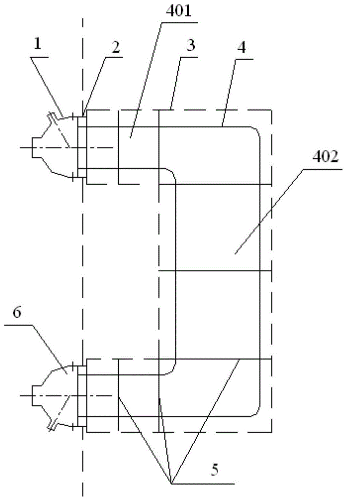
[0015] Such as figure 1 As shown, the passive waste heat discharge heat exchanger of the pressurized water reactor nuclear power plant is set in the refueling water tank, which includes the upper inlet head 1, the lower outlet head 6 and the "C"-shaped vertical heat exchanger connecting the upper and lower heads Tube bundle 4; the "C"-shaped vertical heat exchange tube bundle 4 includes several "C"-shaped heat-exchange tubes of different sizes, and the several "C"-shaped heat-exchange tubes

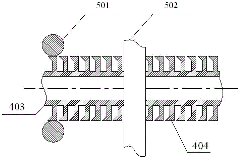
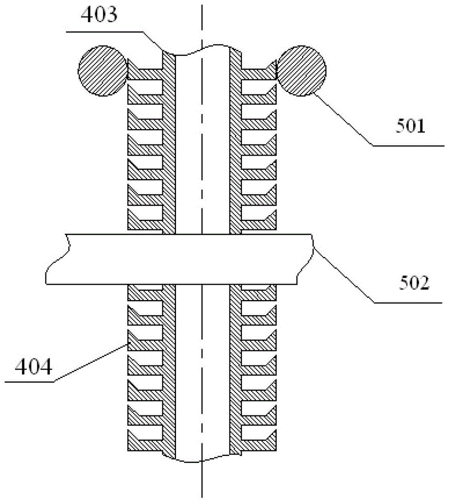
[0016] The tube bundle is fixed by multiple rows of anti-vibration strips, which allow the tubes to expand and contract axially to absorb thermal expansion of the tubes. After being put into use, the medium in the tube side is the primary circuit coolant, and the outside of the tube is the normal temperature water in the refueling water tank. After being put into ...


PUM


Abstract

The invention relates to a finned tube heat exchanger. The finned tube heat exchanger is arranged in refueling water tank of a passive waste heat removal system of a nuclear power station and comprises a C-shaped vertical pipe bundle, a support and anti-vibration strips for fixing a heat exchange pipe bundle, wherein the C-shaped vertical pipe bundle is composed of a plurality of C-shaped heat exchange pipes, and a plurality of anti-vibration strip arrangement regions are arranged in the C-shaped vertical pipe bundle. Cylindrical anti-vibration strips are arranged in the anti-vibration strip arrangement regions. The manufacturing cost and difficulty of the heat exchanger in the passive waste heat removal system of the pressurized water reactor nuclear power station can be reduced, the stress concentration situation of the heat exchanger heat transfer pipes during operation is effectively reduced, the heat transfer pipe bundle constraint and heat transfer pipe corrosion probabilities are reduced, and accordingly the risk that the heat transfer pipe bundle deforms and is invalid is reduced.

Description

technical field [0001] The invention relates to the field of pressurized water reactor nuclear power plants, in particular to a finned tube heat exchanger applied to a secondary side passive waste heat discharge system. Background technique [0002] The passive waste heat removal heat exchanger of the pressurized water reactor nuclear power plant is an important equipment of the passive waste heat removal system. Multiple rows of anti-vibration strips are fixed, and the anti-vibration strips allow the pipe to expand and contract axially to absorb the thermal expansion of the pipe. After being put into use, the medium of the tube side is the primary circuit coolant, and the outside of the tube is the normal temperature water in the refueling water tank. After being put into use, the refueling water in the refueling water tank gradually heats up until it boils. [0003] In the past, the passive exhaust heat exchanger in the pressurized water reactor nuclear power plant used a...

Claims


Application Information

Patent Timeline
Patent Type & Authority Patents(China)
IPC IPC(8): F28D1/04F28F1/30F28F9/013
Inventor 李焕鸣邓丰黄燕
Owner NUCLEAR POWER INSTITUTE OF CHINA
Why Eureka
Try Eureka