
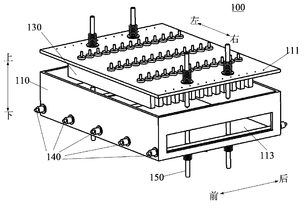
PECVD apparatus

A technology of equipment and cavity, which is applied in the field of ions, can solve the problems of increasing the cost of raw materials and processing costs and difficulties, affecting the appearance and quality of cells, and deteriorating the uniformity of plate airflow, so as to weaken the standing wave effect and structure Simple, productivity-increasing effect

Active Publication Date: 2014-06-18
BEIJING NAURA MICROELECTRONICS EQUIP CO LTD
View PDF7 Cites 9 Cited by
  • Summary
  • Abstract
  • Description
  • Claims
  • Application Information

AI Technical Summary

Problems solved by technology

[0006] First of all, the particles generated during the process, or the particles peeled off from the upper electrode after long-term operation, will fall on the film-forming surface, affecting the appearance and quality of the cell;
[0007] Secondly, in order to obtain greater production capacity, the area of ​​the carrier plate in this method is relatively large, and generally dozens or even hundreds of solar cells can be placed, so the equipment occupies a large area and is difficult to maintain;
[0008] Third, in order to obtain greater production capacity, the size of the equipment continues to increase, Image 6 The size of the upper and lower plates of the shown CCP device will also increase accordingly, which will increase the standing wave effect on the plate, and will lead to the deterioration of the airflow uniformity in the middle and edge of the plate, which will affect the process bad effect
In addition, the increase in the size of equipment and parts increases the cost of raw materials and processing costs and difficulties

Method used


Image

  • PECVD apparatus
  • PECVD apparatus
  • PECVD apparatus

Examples


Embodiment Construction

[0030] Embodiments of the present invention are described in detail below, examples of which are shown in the drawings, wherein the same or similar reference numerals designate the same or similar elements or elements having the same or similar functions throughout. The embodiments described below by referring to the figures are exemplary and are intended to explain the present invention and should not be construed as limiting the present invention.

[0031] In describing the present invention, it should be understood that the terms "center", "longitudinal", "transverse", "length", "width", "thickness", "upper", "lower", "front", " Orientation or position indicated by "back", "left", "right", "vertical", "horizontal", "top", "bottom", "inner", "outer", "clockwise", "counterclockwise", etc. The relationship is based on the orientation or positional relationship shown in the drawings, and is only for the convenience of describing the present invention and simplifying the descrip...


PUM


Abstract

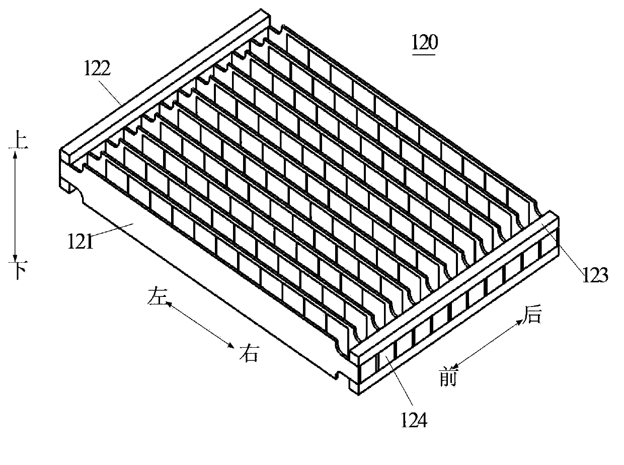
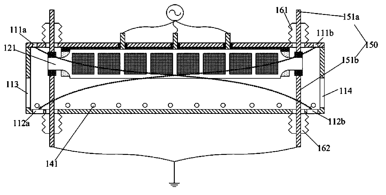
The invention provides a PECVD apparatus. The apparatus comprises a cavity, a wafer carrier, a plurality of radio frequency electrodes, a transmission device and a lifting device. The cavity is provided with a gas inlet and a gas outlet, and is also provided with a first transmission hole and a second transmission hole; the wafer carrier includes a plurality of carrying plates vertically arranged in a spaced manner along a fore-and-aft direction, and the wafer carrier can vertically move between an upper portion position and a lower portion position in a reaction chamber; and the radio frequency electrodes are arranged at the top of the reaction chamber and are perpendicular to the top surface, the radio frequency electrodes are arranged in a spaced manner along a fore-and-aft direction, and the radio frequency electrodes are correspondingly inserted into a space between adjacent carrying plates when the wafer carrier is positioned in the upper position of the reaction chamber. The PECVD apparatus has the advantages of productivity increase, occupied area reduction, processing difficulty and cost reduction, weakening of the standing wave effect on the radio frequency electrodes, and film surface quality improvement.

Description

technical field [0001] The invention relates to the field of plasma technology, in particular to a PECVD (Plasma Enhanced Chemical Vapor Deposition) equipment. Background technique [0002] With the continuous development of plasma (Plasma) technology, plasma devices have been widely used in the manufacturing process of integrated circuits (IC) or photovoltaic (PV) products. , referred to as CCP) device discharge principle is simple, compared with ECR (electron cyclotron resonance plasma), ICP (inductively coupled plasma) generated plasma is more uniform, so it has been widely used in the PV industry. [0003] The flat-plate PECVD equipment used in the manufacturing process of photovoltaic crystalline silicon products is mainly divided into direct method and indirect method according to the different film forming methods. Both direct and indirect methods have advantages and disadvantages. The direct method forms a dense film, which can realize surface passivation and bulk ...

Claims


Application Information

Patent Timeline
Patent Type & Authority Applications(China)
IPC IPC(8): C23C16/44C23C16/455C23C16/458
Inventor 张风港
Owner BEIJING NAURA MICROELECTRONICS EQUIP CO LTD
Learn More