
Method for producing carbonized material by means of carbonizing converter

A carbonized material and converter technology, which is applied in chemical instruments and methods, biofuels, coke ovens, etc., can solve the problems of increasing fuel costs, increasing exhaust gas emissions, and inconvenient production, and achieves the effect of reducing energy consumption and reducing emissions

Active Publication Date: 2014-06-18
淮北中清环保科技有限公司
View PDF6 Cites 20 Cited by
  • Summary
  • Abstract
  • Description
  • Claims
  • Application Information

AI Technical Summary

Problems solved by technology

At present, most of the carbonization converters that produce carbonized materials need to burn fuel to provide heat for the carbonization furnace. The dry distillation gas from the pyrolysis of raw materials is discharged from the feed end. Since the pyrolysis gas contains a large amount of tar, the temperature of the feed end is low, and the dry distillation gas Most of the tar in the retort gas condenses into a liquid state when it is discharged from the feed end, and is mixed with the raw materials to form agglomerates, resulting in blockage of the carbonization furnace, requiring shutdown of the furnace to remove slag, causing inconvenience to production, and increasing additional production due to shutdown The cost of dry distillation gas produced by pyrolysis of raw materials is directly discharged after additional incineration or steam generated by waste heat boiler, which not only increases fuel costs, but also increases exhaust gas emissions, which is neither energy-saving nor environmentally friendly

Method used


Image

  • Method for producing carbonized material by means of carbonizing converter

Examples


Embodiment Construction

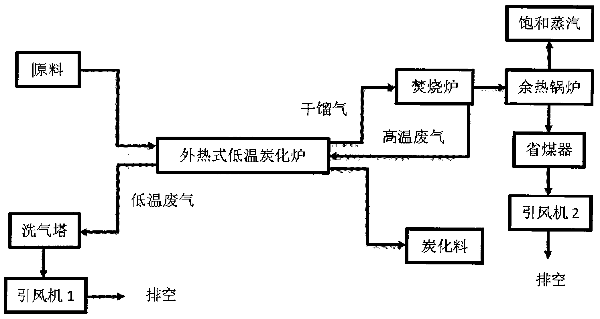
[0012] Such as figure 1 As shown, a method for producing carbonized materials using a carbonization converter, the steps are as follows: feed raw materials from the feed end of the carbonization converter, and heat the raw materials step by step in the product channel of the carbonization converter, slowly heating from normal temperature to 400 ° C ~ 600 ° C , the raw material is dried, pyrolyzed and solidified in the product channel of the carbonization furnace to produce carbonized material, which is discharged from the discharge end of the carbonization converter; the dry distillation gas volatilized during the drying, pyrolysis and solidification process of the raw material is controlled by negative pressure It moves in the same direction as the raw material, and is drawn into the incinerator through the pipe connected to the incinerator at the discharge end of the carbonization converter for incineration; part of the high-temperature gas generated after the incineration of...


PUM


Abstract

The invention discloses a method of producing a carbonized material by means of a carbonizing converter. The method comprises the following steps: feeding a raw material from the feed inlet of the carbonizing converter; gradually heating the raw material in a product channel of the carbonizing converter from normal temperature to 400-600 DEG C slowly; drying, pyrolysing and curing the raw material in the product channel of the carbonizing converter to produce the carbonized material and discharging the carbonized material from the discharge port of the carbonizing converter; moving the retorting gas volatilized in the drying, pyrolysing and curing process of the raw material orthokinetically with the raw material through negative pressure control; feeding the retorting gas into a combustion device through a pipeline arranged at the discharge port of the carbonizing converter; and introducing a part of high temperature gases generated by combustion to the product channel of the carbonizing converter to heat the raw material through the air inlet pipe arranged at the discharge port of the carbonizing converter. According to the method, the flow direction of the raw material is contrary to that of the high temperature exhaust gas but is orthokinetic with the retorting gas, so that not only is the quality improved, but also agglomeration is prevented. Meanwhile, fuel is not supplemented, so that the energy consumption is reduced, the emission is reduced, and the method is more energy-saving and environment-friendly.

Description

technical field [0001] The invention relates to a method for producing carbonized material, in particular to a method for producing carbonized material using a carbonization converter. Background technique [0002] The low-temperature carbonization process is to heat the raw materials to reduce most of the non-carbon elements, and the released carbon elements are combined into ordered crystalline products known as basic graphite crystallites. At present, most of the carbonization converters that produce carbonized materials need to burn fuel to provide heat for the carbonization furnace. The dry distillation gas from the pyrolysis of raw materials is discharged from the feed end. Since the pyrolysis gas contains a large amount of tar, the temperature of the feed end is low, and the dry distillation gas Most of the tar in the retort gas condenses into a liquid state when it is discharged from the feed end, and is mixed with the raw materials to form agglomerates, resulting in...

Claims


Application Information

Patent Timeline
IPC IPC(8): C10B53/00C10B53/02C10B57/18C01B31/08C01B32/312C01B32/39
CPCY02E50/10
Inventor 席轶梁大明张伟奇
Owner 淮北中清环保科技有限公司
Learn More