
Control system of alternating current servo permanent magnet synchronous motor

A permanent magnet synchronous motor and AC servo technology, applied in the control system, vector control system, motor generator control, etc., can solve the problems of inability to adapt, inconvenient installation and debugging, etc., achieve safe and reliable performance, and overcome the influence of environmental conditions , the effect of simple structure

Inactive Publication Date: 2014-06-11
XINXIANG XIAFENG ELECTRIC LTC
View PDF0 Cites 12 Cited by
  • Summary
  • Abstract
  • Description
  • Claims
  • Application Information

AI Technical Summary

Problems solved by technology

[0002] Servo motors are divided into DC servo motors and AC servo motors. Among them, AC servo motors are divided into asynchronous and synchronous. DC motors and synchronous motors are generally permanent magnet structures. They all require sensors or encoders to be loaded on the rotating motor. Obtain the current rotor speed and position of the motor, so as to realize real-time and high-precision control of the motor. Among them, the AC servo permanent magnet synchronous motor has the best torque performance and the highest control accuracy, and is widely used in high-end fields such as CNC machine tools. It needs to install a sensor on the motor side, and the sensor signal is then transmitted to the controller side, which is easily affected by environmental conditions such as vibration, and is inconvenient to install and debug. It is only suitable for indoor occasions and cannot adapt to harsh environments such as oil fields, coal mines, and mines.

Method used


Image

  • Control system of alternating current servo permanent magnet synchronous motor
  • Control system of alternating current servo permanent magnet synchronous motor
  • Control system of alternating current servo permanent magnet synchronous motor

Examples


Embodiment Construction

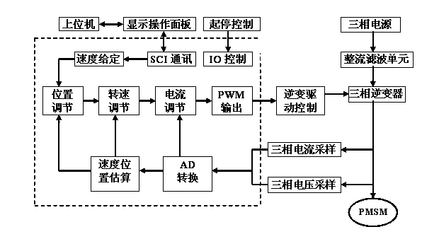
[0016] The present invention is described in further detail in conjunction with accompanying drawing, as figure 1 As shown in the figure, the rectification and filtering unit rectifies the three-phase alternating current into direct current through the full bridge. Four electrolytic capacitors are used between the positive and negative poles, two in parallel and two in series. The positive and negative poles of each capacitor are connected in parallel with a power resistor to maintain mutual Charge and discharge balance, effectively reducing the ripple of the DC bus.

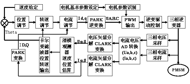
[0017] The interior of the dotted line box is divided into a core operation control unit. This part is mainly for centralized operation and processing of digital and analog signals collected from various channels. The main chip adopts a 32-bit DSP data signal processor of TI Company, and the processing signals include external input and output switches. Control start and stop; input analog quantities such as fre...


PUM


Abstract

The invention discloses a control system of an alternating current servo permanent magnet synchronous motor. The control system comprises a rectification filtering unit, a three-phase inverter, a core computing control unit, an inversion driving control circuit and a communication monitoring control part. The communication monitoring control part is composed of a display operation panel and a starting-stopping control part, the display operation panel is in signal connection with the core computing control unit, the starting-stopping control part is connected with one input end of the core computing control unit, one output end of the core computing control unit is connected with the input end of the inversion driving control circuit, the output end of the inversion driving control circuit is connected with one input end of the three-phase inverter, a three-phase power source is connected with the other input end of the three-phase inverter through the rectification filtering unit, the output end of the three-phase inverter is respectively connected with the input end of a data collecting circuit and the input end of the alternating current servo permanent magnet synchronous motor, and the output end of the data collecting circuit is connected with the other input end of the core computing control unit.

Description

technical field [0001] The invention relates to a motor control system, in particular to an AC servo permanent magnet synchronous motor control system. Background technique [0002] Servo motors are divided into DC servo motors and AC servo motors. Among them, AC servo motors are divided into asynchronous and synchronous. DC motors and synchronous motors are generally permanent magnet structures. They all require sensors or encoders to be loaded on the rotating motor. Obtain the current rotor speed and position of the motor, so as to realize real-time and high-precision control of the motor. Among them, the AC servo permanent magnet synchronous motor has the best torque performance and the highest control accuracy, and is widely used in high-end fields such as CNC machine tools. It needs to install a sensor on the motor side, and the sensor signal is transmitted to the controller side. It is easily affected by environmental conditions such as vibration, and it is inconvenien...

Claims


Application Information

Patent Timeline
IPC IPC(8): H02P21/00
Inventor 李德印熊健伟田明吉李大鹏石兴华
Owner XINXIANG XIAFENG ELECTRIC LTC
Learn More