Splicing I-shaped tube and pull grid door and window sash splicing grid bar manufactured by same

A jointing and splicing technology, applied in the direction of shutters/movable grilles, etc., can solve the problems of large human injury, poor impact bending and torsional strength, and many troublesome production processes, so as to improve applicability and aesthetics. High strength, high bending and torsional strength, convenient for standardized production

Active Publication Date: 2014-06-11
吴远文
View PDF6 Cites 0 Cited by
  • Summary
  • Abstract
  • Description
  • Claims
  • Application Information

AI Technical Summary

Problems solved by technology

[0005] 1. During the welding (argon arc welding) process of stainless steel welded rectangular tubes and the bars made of them, a large amount of welding fumes and ozone will be produced, as well as ultraviolet radiation 5 to 30 times higher than that of ordinary welding, which will cause great harm to the human body ;
[0006] 2. The welding parts need to be ground and polished, and a large amount of dust will be generated, which will cause great pollution to the environment;
[0007] 3. The production process is troublesome and the production cost is high;
[0008] 4. The finished grid pole has low precision, easy deformation, loose structure, poor impact bending and torsional strength, not firm, loud noise during use, and not smooth enough to move
After the pivot and sliding shaft are connected in series, they cannot be normally placed in the longitudinal cavity of the grid rod, and if riveted, the rivet head will be exposed outside, which will affect the appearance of the grid door and window sash

Method used


Image

  • Splicing I-shaped tube and pull grid door and window sash splicing grid bar manufactured by same
  • Splicing I-shaped tube and pull grid door and window sash splicing grid bar manufactured by same
  • Splicing I-shaped tube and pull grid door and window sash splicing grid bar manufactured by same

Examples


Embodiment 1

[0045] Embodiment 1 (inlaid I-shaped tube)

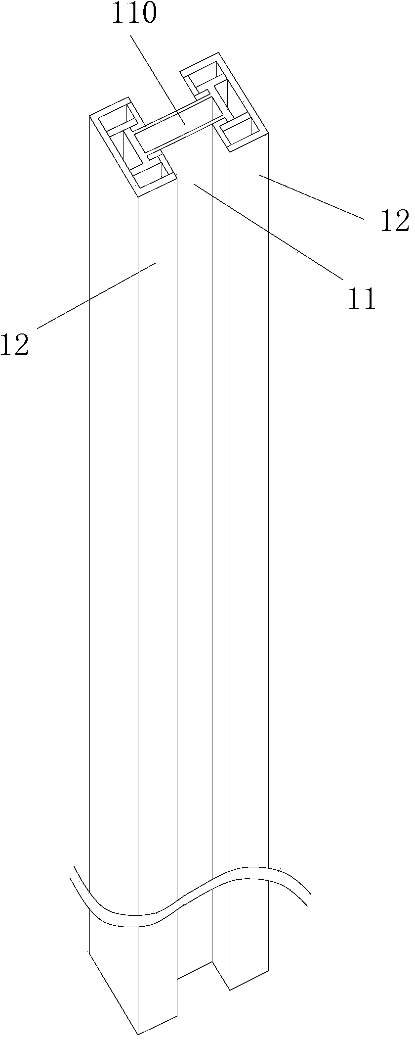
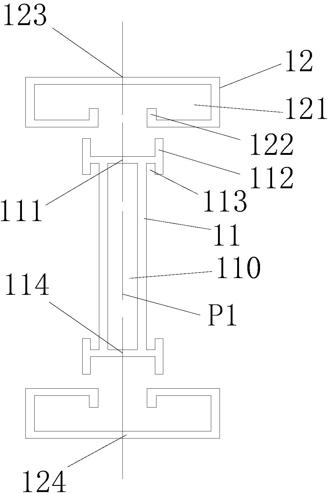
[0046] seefigure 1 and 2 , The inlaid I-shaped pipe described in this embodiment is provided with one connecting part 11 and two symmetrically arranged side inlaid parts 12 .

[0047] The coupling part 11 is provided with a longitudinal transparent cavity 110, and the ends of the coupling part 11 on both sides in the longitudinal direction have a longitudinal joint structure with a longitudinal joint strip 112 and a longitudinal joint groove 113, and the side joint part 12 has a There is a longitudinal seaming structure of the longitudinal seaming groove 121 and the longitudinal seaming bar 122 matched with the coupling part 11, and the coupling part 11 and the two side seaming parts 12 are separated from each other through the respective longitudinal seaming structures. Join and extend longitudinally through the seams. The cross-sectional structure of the spliced ​​I-shaped pipe is longitudinal axis symmetric and transverse axis ...

Embodiment 2

[0049] Embodiment 2 (inlaid I-shaped tube)

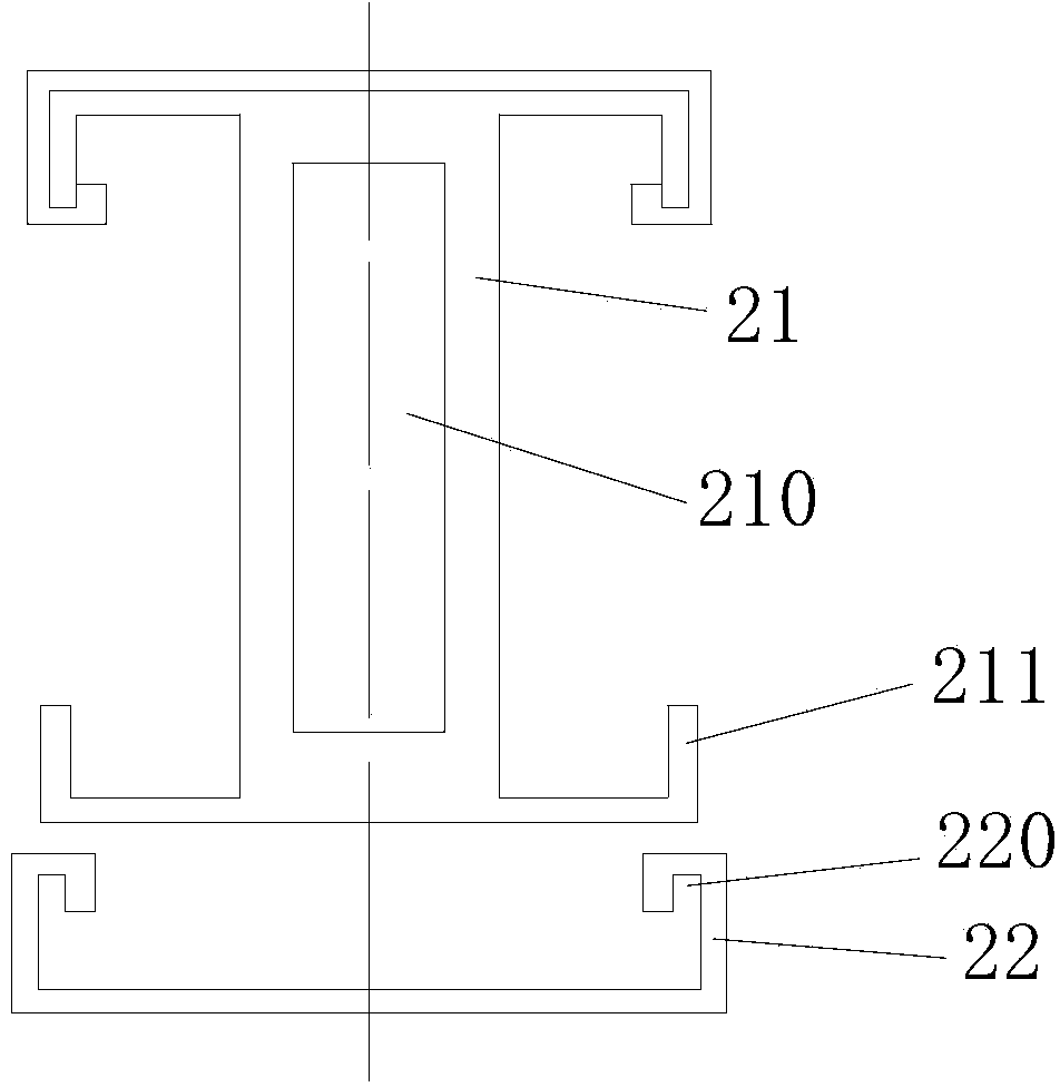
[0050] see image 3 , similar to Embodiment 1, the difference is that there is only one side fitting part 22, and only one side end of the connecting part 21 is provided with a longitudinal fitting structure with a fitting strip 211. The side setting part 22 is provided with a fitting groove 220 . The coupling part 21 is only interspersed with one side setting part 22 along the longitudinal direction. The fitting strip 211 fits with the fitting groove 220 . The structure of the connecting part 21 and the side setting part 22 after inserting and fitting is the same as that of the other end of the connecting part 21 . The connecting part 21 and the side setting part 22 are also jointed along the longitudinal direction. Reference 210 designates the longitudinal through cavity of the coupling part 21 . The cross-sectional structure of the spliced ​​I-shaped pipe is symmetrical to the longitudinal axis.

Embodiment 3

[0051] Embodiment 3 (inlaid I-shaped tube)

[0052] see Figure 4 , similar to Embodiment 1, the difference is that the longitudinal embedding strips 311 at both ends of the coupling member 31 surround a rectangular ring groove 3111 . The fitting strips 311 at both ends of the coupling part 31 are matched with the fitting grooves 321 of the side fitting part 32 . The connecting part 31 and the side setting part 32 are also jointed along the longitudinal direction. Reference 310 designates the longitudinal through cavity of the coupling part 31 .


PUM


Abstract

The invention discloses a splicing I-shaped tube and a pull grid door and window sash splicing grid bar manufactured by the same and relates to pull grid door and window. The splicing I-shaped tube is provided with a connection component and at least one side splicing component, wherein the connection component is provided with a longitudinal through cavity in the longitudinal direction and a longitudinal splicing structure with a longitudinal splicing groove or/and a longitudinal splicing bar along the longitudinal side end part; the side splicing component is provided with a longitudinal splicing structure with a longitudinal splicing bar which is matched with the connection component and/or a longitudinal splicing groove in the longitudinal direction; the connection component and the side splicing component are mutually spliced at the end parts by the respective longitudinal splicing structures and are spliced by longitudinally expanding and intersecting; the cross section of the splicing I-shaped tube is I-shaped; the axle wire of the front and rear direction of the cross section of the splicing I-shaped tube penetrates through at least four wall layers. The splicing grid bar is provided with the splicing I-shaped tube which is provided with one connection component and the at least one side splicing component. The precision is high, the structure is steady, the deformation is not easily caused, and the anti-impacting and bending performance and the torsional strength are high.

Description

technical field [0001] The invention relates to a sash door and window, in particular to an inlaid I-shaped pipe and an inlaid grid bar of the sash of a sash made of the same. Background technique [0002] Due to its unique structure, the sliding door and window sashes can be ventilated without affecting the lighting, and can play the role of protection, anti-intrusion and decoration, and it is also convenient for fire protection, so it is widely used. [0003] Existing sash doors and windows are generally composed of the main part, the grid bar, and a connector, a pivot, a sliding shaft, a puller and a frame. As the main component, the grid pole has a core function. There are three basic technical conditions commonly used in the industry: first, the pivot and sliding shafts are placed in the grid bar movably, and the shaft heads at both ends of the pivot and sliding shafts are not exposed; The shaft holes are respectively connected with the pivot shaft and the sliding sha...

Claims


Application Information

Patent Timeline
Patent Type & Authority Applications(China)
IPC IPC(8): E06B9/02
Inventor 吴远文
Owner 吴远文
Why Eureka
Try Eureka