
Heat-preserving electrolytic tank

A technology of electrolytic cells and heat preservation covers, which is applied in the field of heat preservation electrolytic cells, can solve the problems of affecting the workshop environment, high labor intensity, and large heat loss, and achieve the effects of improving environmental benefits, reducing labor intensity, and improving work efficiency

Active Publication Date: 2014-05-28
YUNNAN RUNXIN ALUMINUM
View PDF23 Cites 9 Cited by
  • Summary
  • Abstract
  • Description
  • Claims
  • Application Information

AI Technical Summary

Problems solved by technology

When performing the above operations, a large number of manual shelling operations are required, which is not only labor-intensive, time-consuming, and heat loss is large, but also the insulation covering material will inevitably fall into the electrolytic cell during the operation, thereby destroying the electrolytic tank. Electrolyzer heat balance and material balance affect the quality of electrolytic products
In addition, due to the large amount of thermal insulation material attached to the residual anode carbon block replaced from the current electrolytic cell, a large amount of dust will be generated during the electrolysis workshop, transportation process and cleaning of the residual anode carbon block, which not only seriously affects the workshop environment, but also increases Material consumption cost per ton of aluminum
The current feeding method of the pre-baked aluminum electrolytic cell will prevent the rapid dissolution and diffusion of alumina, thus affecting the smooth and efficient operation of the electrolytic production

Method used


Image

  • Heat-preserving electrolytic tank
  • Heat-preserving electrolytic tank
  • Heat-preserving electrolytic tank

Examples


Embodiment Construction

[0020] The present invention will be further described below in conjunction with the accompanying drawings.

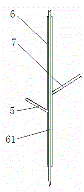
[0021] The thermal insulation electrolytic cell provided by the present invention comprises a cell body 1 and its upper part, an anode carbon block 10 fixed on the cell body 1, a gas collecting hood 8 fixed on the upper part of the cell, and a feeding pipe fixed in the middle of the gas collecting hood 8 6. The shelling hammer 61 passing through the feeding pipe 6, the upper end of the shelling hammer 61 is connected to the power cylinder, the side roof and side wall of the tank body 1 are movable insulation tank covers 2, and the anode carbon block 10 is fixed on the horizontal bus bar at the upper part of the tank 11, the top of the tank body 1 is provided with a thermal insulation cover 3, and the thermal insulation cover 3 is connected with the gas collection cover 8 through the connector 4, as figure 1 , 4 The movable heat preservation tank cover 2 comprises a me...


PUM


Abstract

The invention provides a heat-preserving electrolytic tank. The heat-preserving electrolytic tank comprises a tank body, an upper tank part, an anodic carbon block, a gas collecting hood, a blanking pipe and a shell breaking hammer, wherein the anodic carbon block is fixed on an upper horizontal bus of the tank body; the gas collecting hood is fixed at the upper tank part; the blanking pipe is fixed in the middle of the gas collecting hood; the shell breaking hammer penetrates through the blanking pipe. The heat-preserving electrolytic tank is characterized in that movable heat-preserving tank hoods are arranged at the side top and on the side wall of the tank body; a heat-preserving cover plate is arranged at the middle top of the tank body and is connected with the gas collecting hood through a connecting piece. Existing heat-preserving coverage material such as oxidation alumina, a face shell block and an electrolyte block is replaced with the quickly-replaceable movable heat-preserving hoods and does not need to be frequently added, so that the labor strength is reduced, the working efficiency is improved, heat losses are reduced, and damage to electrolytic tank heat balance and material balance caused by the fact that heat-preserving coverage material falls into the electrolytic tank in the anode replacement and heat-preserving material adding processes is avoided; moreover, the environmental pollution can be greatly reduced, and the problem that the alumina cannot be quickly dissolved and diffused, which is caused by that fact blanking is performed only from a middle seam of a large pre-roasting aluminum electrolytic tank is solved.

Description

[0001] technical field [0002] The invention relates to a thermal insulation electrolytic cell, which belongs to the technical field of electrolysis. technical background [0003] As far as the existing molten salt electrolytic aluminum smelting technology is concerned, since the early 1980s, after nearly 30 years of development, it has reached a quite advanced level. However, the traditional industrial electrolytic aluminum technology is still facing major innovations, especially the research and development of energy-saving and environmentally friendly aluminum electrolytic cells with new structures, which has become the mainstream of future electrolytic cell technology development, such as cathode carbon block multi-steel rod technology, aluminum electrolytic cell super magnetic field stability technology and more. In the current aluminum electrolysis production process, alumina, surface shell blocks and electrolyte blocks are used as thermal insulation covering materia...

Claims


Application Information

Patent Timeline
Patent Type & Authority Applications(China)
IPC IPC(8): C25C3/08
Inventor 杨万章余凯陈本松
Owner YUNNAN RUNXIN ALUMINUM
Learn More