Patient specific anatomically correct implants to repair or replace hard or soft tissue

Inactive Publication Date: 2006-06-22
PIETRZAK WILLIAM
View PDF0 Cites 241 Cited by
  • Summary
  • Abstract
  • Description
  • Claims
  • Application Information

AI Technical Summary

Benefits of technology

[0006] It has now been discovered that, using technology derived from rapid prototyping of parts with CNC machining technology, a database can be constructed from a series of body imaging scans of the affected area in an individual, and an implant can be made specifically for the individual recipient, in a matter of days if necessary. This would reduce time scheduled for surgery as well, by reducing the amount of time required to ready the patient and implant for the actual implantation process, achieving a better fit that optimizes the correct anatomical geometry necessary for the body to function without compensating for the implant.
[0009] The present invention has many advantages. The implants and methods according to various embodiments of the invention facilitate tissue replacement surgery such as knee replacement surgery. A custom-made implant according to an embodiment of the invention can be constructed specifically for an individual recipient. If necessary, the custom-made implant can be produced according to the disclosed system in a matter of days. To the great advantage of the patient and surgeon, use of an embodiment of the invention reduces the time interval between the trauma to an area and the surgery. This increases the probability of success of the surgical repair. Use of an embodiment of the invention also helps avoid secondary wear on other parts of the body that are attempting to compensate for the inaccurate geometry that can arise from off-the-shelf, or “close match” implants. It also reduces open time at the site to minimize trauma and the chance for infection.

Problems solved by technology

Development of such implants has not yet occurred due to the potentially low return on investment.
Existing wrist replacement technologies require removal of carpas and penetration or removal of the distal articular cartilage of the radius to implant them, thereby causing degradation of joint strength and ROM.

Method used


Image

  • Patient specific anatomically correct implants to repair or replace hard or soft tissue
  • Patient specific anatomically correct implants to repair or replace hard or soft tissue
  • Patient specific anatomically correct implants to repair or replace hard or soft tissue

Examples


Embodiment Construction

[0020] A description of preferred embodiments of the invention follows. It will be understood that the particular embodiments of the invention are shown by way of illustration and not as limitations of the invention. At the outset, the invention is described in its broadest overall aspects, with a more detailed description following. The features and other details of the compositions and methods of the invention will be further pointed out in the claims.

[0021] The present invention is directed to custom-made implants and methods of preparing a custom-made implant to repair tissue in a living individual. Table 1 summarizes steps in the disclosed system.

TABLE 1Progression of process of development for patient specific implant.

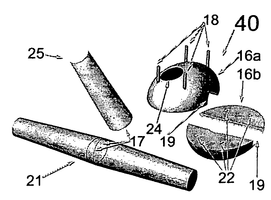
[0022] An implant, for example, a bone that is part of a complex joint, according to an embodiment of the invention, may have a structure that does not reflect the actual biological component it is designed to replace.

[0023] An example of a disclosed implant ...


PUM


Abstract

The present invention relates to a system of preparing a one of a kind artificial or biological implant to repair or replace a bone or a tissue part in a living individual, the system comprising: pre-operatively constructing an anatomically correct, affected area 7-unique scan implants geometry, wherein the implants geometry is unknown before the acquisition of the individual's data; and using a process derived from rapid prototyping to construct a geometrically and anatomically correct duplication of the functional attributes of the bone or tissue part to be replaced from the dataset created by scans of the recipients scans. This system can also be used to modify, pre-operatively, existing FDA approved implants.

Description

RELATED APPLICATION [0001] This application claims the benefit of U.S. Provisional Application No. 60 / 637,320 filed on Dec. 17, 2004, the teachings of which are incorporated herein by reference in their entirety.BACKGROUND OF THE INVENTION [0002] Although current joint repair and joint replacement technology allows for computerized tomography (CT) or magnetic resonance imaging (MRI) scans to be voxelized, that is, converted to computer generated 3D models, for simulation in order to allow the surgical team to select the optimal size and orientation of an implant, the implant and the living tissue to which it attaches must be modified in the operating room to obtain the best possible fit and Range of Motion (ROM). Orthopedic repair or reconstructive surgery is still in its early stages of development. Presently, there is no viable technique to replace small bones in the wrist, foot, vertebrate or ankle to allow for normal ROM. The end goal of all implant surgery is to obtain permanen...

Claims


Application Information

Patent Timeline
IPC IPC(8): A61F2/08A61F2/30G06F19/00
CPCA61F2/30942A61F2/38A61F2/44A61F2/442A61F2002/30708A61F2002/30945A61F2002/30952A61F2002/30957A61F2002/30958A61F2002/30962A61F2002/4271A61F2002/4289A61F2002/4292A61F2250/0084A61F2310/00017A61F2310/00023G06F19/3437A61F2002/30943B33Y80/00G16H50/50
Inventor PIETRZAK, WILLIAM
Owner PIETRZAK WILLIAM
Why Eureka
Try Eureka