
Synchronizing shaft error compensation method of numerical control gear manufacturing machine tool

An error compensation and synchronous shaft technology, applied in the direction of gear cutting machines, gear teeth, manufacturing tools, etc., can solve the problems of inability to realize synchronous shaft error compensation, inability to actively control synchronous shafts, complicated implementation steps, etc., and achieve a small amount of real-time exchange data. , to achieve concise, adaptable and scalable effects

Active Publication Date: 2014-05-28
CHONGQING UNIV
View PDF7 Cites 8 Cited by
  • Summary
  • Abstract
  • Description
  • Claims
  • Application Information

AI Technical Summary

Problems solved by technology

[0004] The synchronous axis of the electronic gearbox can be divided into the driving axis and the following axis. After the electronic gearbox is enabled, a certain synchronous axis cannot be actively controlled independently. Therefore, the traditional axis error compensation method - the superposition command method cannot realize the synchronous axis. error compensation
At present, there is no method for compensating the error of the synchronous axis of the numerical control gear machine tool. Generally, the pitch error compensation function of the numerical control system is used, but only the static error compensation of the synchronous axis can be realized; for the dynamic error of the machine tool axis, someone proposed An error compensation method based on the offset function of the external coordinate system of the machine tool. This method requires the dual support of hardware and software, and the parameters of the machine tool system need to be modified. The implementation steps are cumbersome

Method used

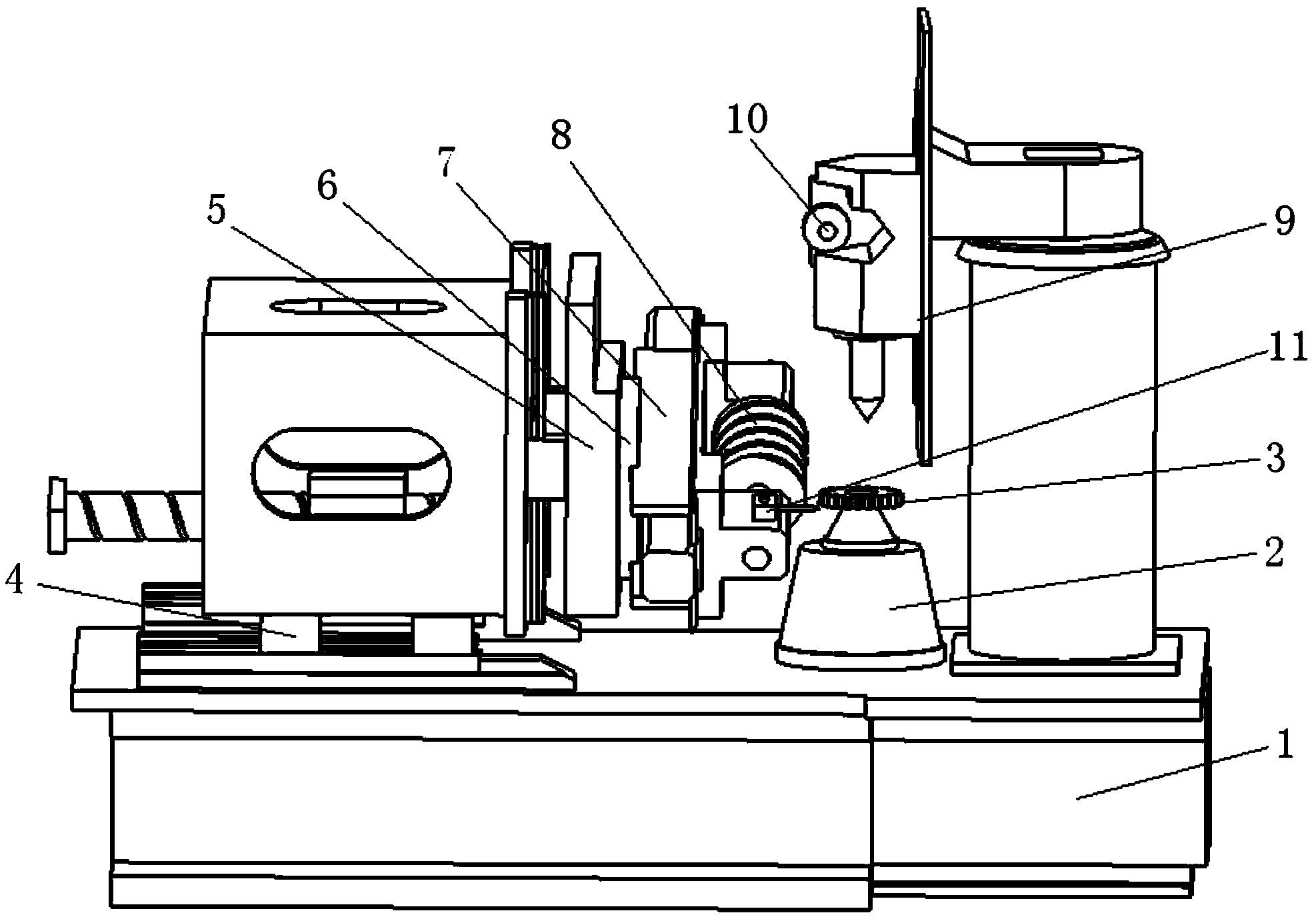
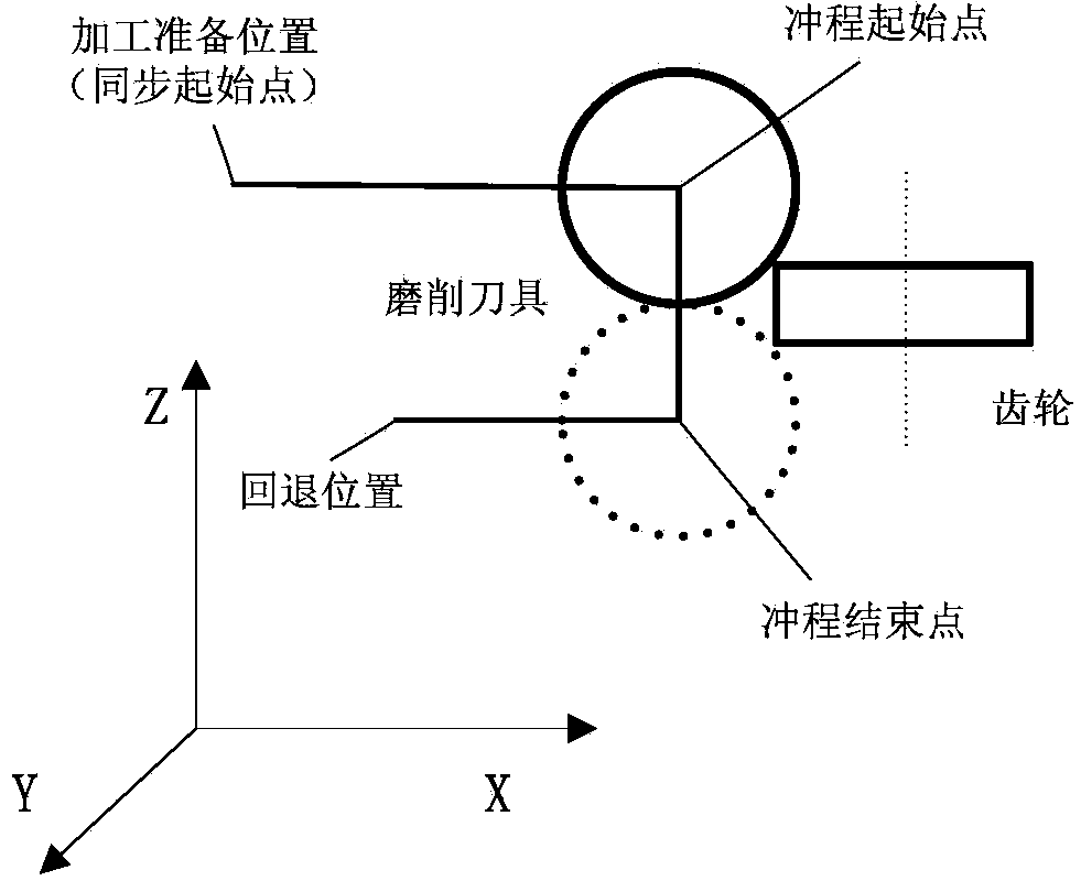

Image

  • Synchronizing shaft error compensation method of numerical control gear manufacturing machine tool
  • Synchronizing shaft error compensation method of numerical control gear manufacturing machine tool
  • Synchronizing shaft error compensation method of numerical control gear manufacturing machine tool

Examples


Embodiment Construction

[0019] The present invention will be described in further detail below in conjunction with the accompanying drawings and specific embodiments.

[0020] Synchronous axis error compensation method for numerically controlled gear machine tools, including virtual axis installation and system parameter setting, setting the motion relationship between virtual axis and synchronous axis and the conversion relationship between virtual axis and synchronous axis, planning of error compensation points and virtual axis Compensation amount calculation and compensation realization method. It specifically includes the following steps:

[0021] 1) By adding a virtual axis as the driving axis in the electronic gearbox of the CNC gear machine tool, and the virtual axis coincides with the following axis in the synchronous axis. Among them, the virtual axis is different from other synchronous axes in the electronic gearbox, and does not point to the actual physical moving parts, so there is no ac...


PUM


Abstract

The invention discloses a synchronizing shaft error compensation method of a numerical control gear manufacturing machine tool. A virtual shaft which is additionally arranged in an electronic gearbox of the numerical control gear manufacturing machine tool is taken as a driving shaft, and coincides with a following shaft in synchronizing shafts; the error compensation amount of each shaft in the synchronizing shafts is converted into an equivalent compensation amount of the virtual shaft by the corresponding synchronization coefficients; the total equivalent compensation amount of the synchronizing shafts is obtained by linear superposition, and finally, the error compensation of the synchronizing shafts is realized by utilizing the theoretical motion of the virtual shaft. According to the method, after the error of each shaft is obtained, the compensation to a single shaft is not needed, the hardware and system parameters of the machine tool are not changed, and the precision needed by the engagement motion of the gear manufacturing can be ensured by only arranging one virtual shaft in the electronic gearbox for compensation; the method is good in flexibility and adaptation, strong in expansion and high in compensation precision, and the composition error at any point in the coordinate system of the machine tool can be compensated; especially, when the dynamic error compensation of the machine tool is carried out, the real-time exchange data amount is small, and the response speed is rapid.

Description

technical field [0001] The invention belongs to the field of gear manufacturing, and relates to the field of digital manufacturing of high-precision gears, in particular to a method for improving the machining accuracy of gears through error compensation for synchronous shafts of gear machine tools. Background technique [0002] The geometric error, thermal error and cutting force error of the machine tool are the key factors affecting the machining accuracy. These three errors can account for about 80% of the total machining error. There are two basic methods to improve the machining accuracy of machine tools: error prevention method and error compensation method. The error prevention method is a "hard technology", which eliminates or reduces possible error sources through design and manufacturing methods, and meets the processing accuracy requirements by improving the manufacturing accuracy of machine tools. The error prevention method has great limitations, and even if i...

Claims


Application Information

Patent Timeline
Patent Type & Authority Applications(China)
IPC IPC(8): B23F23/10
Inventor 李国龙何坤孔二方李先广夏冬刘小旭张汐
Owner CHONGQING UNIV
Learn More