
The load port of the valve control unit independently controls the multi-cylinder flow distribution hydraulic system

A flow distribution and hydraulic system technology, applied in the directions of fluid pressure actuating system components, fluid pressure actuating devices, servo motors, etc., can solve problems such as inability to change flow distribution according to different requirements, inability to intervene in flow distribution, and energy loss. , to achieve good controllability and energy saving, reduce the minimum flow, maintain the effect of the highest pressure flow

Active Publication Date: 2015-09-16
ZHEJIANG UNIV
View PDF5 Cites 0 Cited by
  • Summary
  • Abstract
  • Description
  • Claims
  • Application Information

AI Technical Summary

Problems solved by technology

However, due to the fact that the flow of the traditional flow distribution system is mainly realized by the pressure compensator, diverter valve, and throttle valve, the distribution of flow cannot be intervened, and the function of flow distribution cannot be changed according to different requirements, and unnecessary The energy loss will cause the system to generate serious heat

Method used


Image

  • The load port of the valve control unit independently controls the multi-cylinder flow distribution hydraulic system
  • The load port of the valve control unit independently controls the multi-cylinder flow distribution hydraulic system
  • The load port of the valve control unit independently controls the multi-cylinder flow distribution hydraulic system

Examples


Embodiment Construction

[0023] The present invention will be further described below in conjunction with the accompanying drawings and specific examples.

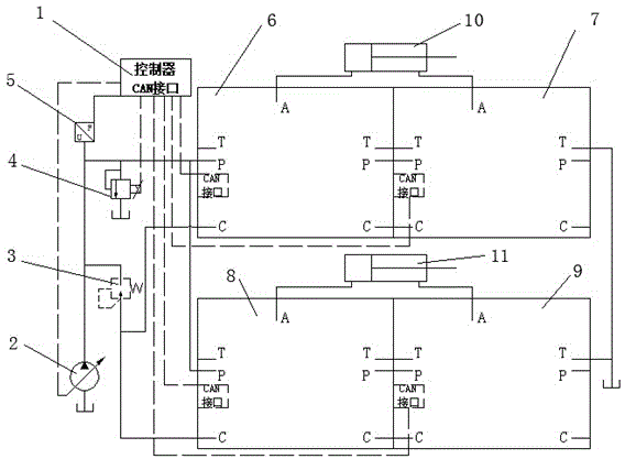
[0024] Such as figure 1 As shown, the present invention includes a controller 1, a variable displacement pump 2, a pressure reducing valve 3, a proportional relief valve 4, a first pressure sensor 5, four valve control units 6, 7, 8, 9 with the same structure, and two The hydraulic cylinders 10, 11; the oil outlet of the variable pump 2 are respectively connected to the oil inlet of the proportional relief valve 4, the oil inlet of the pressure reducing valve 3, the first pressure sensor 5, the oil inlet P of the first valve control unit 6, The oil inlet P of the second valve control unit 7, the oil inlet P of the third valve control unit 8, and the oil inlet P of the fourth valve control unit 9 are connected; the oil outlets of the pressure reducing valve 3 are respectively connected with the first valve control unit 6 The pilot oil port C, the ...


PUM


Abstract

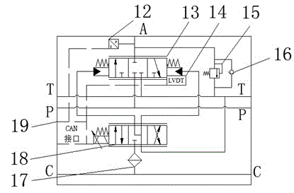
The invention discloses a multi-cylinder flow distribution hydraulic system with independently-controlled valve control unit load ports. An oil outlet of a variable pump is respectively connected with an oil inlet of a proportional overflow valve, an oil inlet of a reducing valve, a first pressure sensor and oil inlets of four valve control units, wherein the oil outlet of the reducing valve is respectively connected with the four valve control unit pilot oil ports, a working port of a first valve control unit is connected with a rodless cavity of a first hydraulic cylinder, a working port of a second valve control unit is connected with a rod cavity of the first hydraulic cylinder, a working port of a third valve control unit is connected with a rodless cavity of the second hydraulic cylinder, a working port of a fourth valve control unit is connected with a rod cavity of the second hydraulic cavity, and a controller is respectively and electrically connected with the variable pump, the proportional overflow valve and CAN interfaces of the four valve control units. Due to the fact that the independently-controlled load ports are adopted, the degree of freedom of the multi-cylinder flow distribution hydraulic system is improved; a second pressure sensor and a valve plug displacement sensor are integrated in each valve control unit so that feedback of pressure flow signals can be accomplished; the multi-cylinder flow distribution hydraulic system can achieve flow distribution on the situation that the flow of the pump is saturated.

Description

technical field [0001] The invention relates to an electro-hydraulic control system, in particular to a hydraulic system for independent control of multi-cylinder flow distribution by load ports of a valve control unit. Background technique [0002] At present, more than 95% of construction machinery adopts hydraulic transmission and control technology. Hydraulic transmission and control technology has become the basic condition to promote the continuous development of construction machinery in the mainstream direction of comfort, reliability, energy saving and intelligence. Among them, the valve control system has always been the mainstream choice of construction machinery due to its high control precision and fast response speed. Therefore, the research and development of valve-controlled flow systems are relatively mature. Currently, widely used valve-controlled systems include open center, closed center, load sensing systems, and LUDV systems. [0003] For construction...

Claims


Application Information

Patent Timeline
Patent Type & Authority Patents(China)
IPC IPC(8): F15B11/17F15B13/02F15B21/04
Inventor 张斌王双俞敏谢科杨华勇
Owner ZHEJIANG UNIV
Learn More