
High-pressure injection module for ordinary hydraulic injection molding machines

A high-pressure injection and injection molding machine technology, applied in the field of high-pressure injection modules, can solve the problems of injection pressure increase, high price, and system pressure should not be too high, and achieve the effect of small changes, low cost of changes, and easy disassembly and assembly

Inactive Publication Date: 2015-08-26
DALIAN UNIV OF TECH
View PDF5 Cites 1 Cited by
  • Summary
  • Abstract
  • Description
  • Claims
  • Application Information

AI Technical Summary

Problems solved by technology

[0003] At present, there are high-pressure injection molding machines for forming thick-walled plastic products or high-viscosity plastic materials on the market, but they are generally more expensive.
As for the common hydraulic injection molding machine which is widely used at present, since this kind of equipment has only one hydraulic system, the actions of mold clamping, plasticizing, injection, pressure maintaining, mold opening and mold closing must be completed sequentially, and the system pressure should not be too high. Thereby limiting the increase of injection pressure of this type of equipment

Method used


Image

  • High-pressure injection module for ordinary hydraulic injection molding machines
  • High-pressure injection module for ordinary hydraulic injection molding machines

Examples


Embodiment Construction

[0011] The present invention will be further described in detail below in conjunction with the accompanying drawings and specific embodiments.

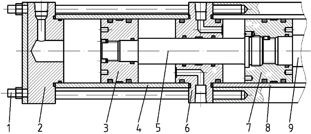
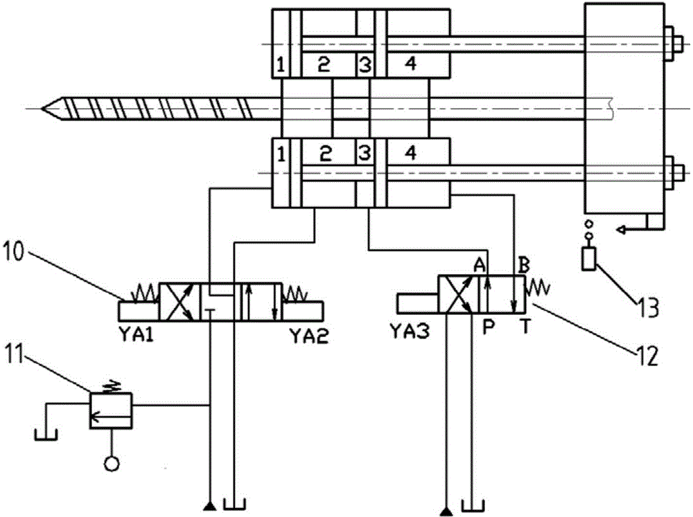
[0012] figure 1 Shown is a hydraulic cylinder for boosting, which is composed of end cover 2, boosting piston 3, boosting cylinder body 4, boosting piston rod 5 and connecting flange 6, etc. The pull rod screw 1 of 6 is connected in series with the original injection molding machine injection hydraulic cylinder cylinder 8. One end of the booster piston rod 5 is connected to the booster piston 3, and the other end is connected to the connecting piston 7 in the cylinder body 8 of the original injection molding machine injection hydraulic cylinder through the connecting flange 6, that is, connected to the original injection molding machine injection piston rod 9 , so as to realize the synchronous action of the booster piston 3 and the connecting piston 7, and the connection methods are all threaded connections.

[0013] Such as figur...


PUM


Abstract

The invention provides a high-pressure injection module for ordinary hydraulic injection molding machines, and belongs to the field of technical innovation of injection molding machines. The high-pressure injection module comprises a pressurization hydraulic cylinder and a control oil way. The pressurization hydraulic cylinder is composed of an end cover, a pressurization cylinder body, a pressurization piston, a pressurization piston rod, a connection flange and the like. The high-pressure injection module is connected with a cylinder body of an existing injection molding machine glue jetting hydraulic cylinder in series through pull rod screws penetrating through the end cover and the connection flange. One end of the pressurization piston rod is connected with the pressurization piston, and the other end of the pressurization piston rod penetrates through the connection flange to be connected with a connection piston in the existing injection molding machine glue jetting hydraulic cylinder, namely an existing molding injection machine glue jetting piston rod, so that synchronous actions of the pressurization piston and the connection piston are achieved. Hydraulic oil required for the actions of the pressurization piston comes form an existing injection molding machine hydraulic system, and the direction of the hydraulic oil is controlled through an electromagnetic reversing valve. Dual safe protection is conducted through an unloading valve and a stroke switch. The high-pressure injection function can be achieved at a low cost through the module, the application range of the injection molding machines is widened, and the existing performance of the injection molding machines is not influenced.

Description

technical field [0001] The invention belongs to the technical transformation field of injection molding machines, and in particular relates to a high-pressure injection module for ordinary hydraulic injection molding machines. Background technique [0002] On the injection molding machine, the polymer is heated and plasticized into a melt, injected into the closed mold cavity at a certain pressure and speed, and the desired product is obtained after pressure maintaining, cooling, and mold opening. There are three main parameter systems in injection molding process control: pressure, time and temperature. Among them, the injection pressure is one of the important indicators of the processing capacity of the injection molding machine, and has a very important influence on the quality of the product. Only under higher injection pressure can the product reach high density and high strength. Therefore, increasing the injection pressure of the injection molding machine is of gre...

Claims


Application Information

Patent Timeline
Patent Type & Authority Applications(China)
IPC IPC(8): B29C45/77
CPCB29C45/77B29C2945/76498B29C2945/76682B29C2945/76859
Inventor 宋满仓常泓刘洋刘冲刘军山赵丹阳
Owner DALIAN UNIV OF TECH
Learn More