
Brake booster

A brake booster and brake boosting technology, which is applied in the direction of brakes, brake transmission devices, brake action activation devices, etc., can solve the problem that the travel sensor is expensive, the travel sensor is difficult to provide high detection accuracy, and the travel sensor has low durability and other problems, to achieve the effect of high axial position detection accuracy, low cost and high signal stability

Active Publication Date: 2014-05-21
BOSCH AUTOMOTIVE PROD SUZHOU
View PDF6 Cites 25 Cited by
  • Summary
  • Abstract
  • Description
  • Claims
  • Application Information

AI Technical Summary

Problems solved by technology

[0007] In such an electric brake booster, it is difficult for the stroke sensor itself to provide high detection accuracy
In addition, travel sensors have low durability and are susceptible to external factors such as magnetic fields, dirt, icing, etc.
In addition, the price of travel sensor is relatively expensive

Method used


Image

  • Brake booster
  • Brake booster
  • Brake booster

Examples


Embodiment Construction

[0034] Preferred embodiments of the present application are described below with reference to the accompanying drawings.

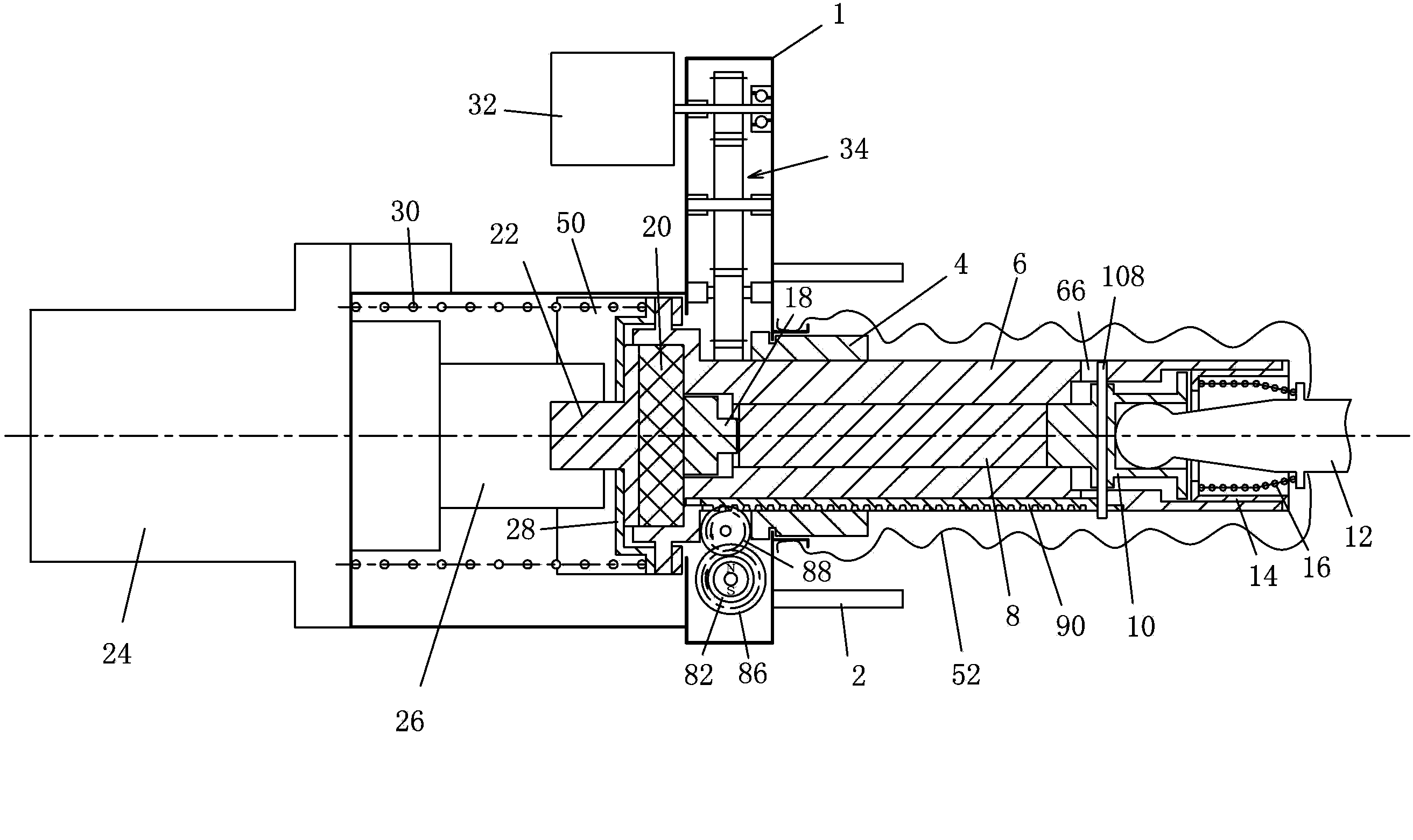
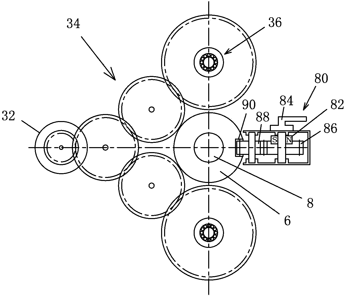
[0035] It should be pointed out that the drawings are only for schematically showing possible implementations of the brake booster of the present application. Therefore, in the drawings, the individual components of the brake booster are not drawn to scale.

[0036] It should also be pointed out that in this application, "near side" or "rear side" refers to the side close to the brake pedal of the vehicle, and "far side" or "front side" refers to the side away from the brake pedal, that is, near the brake pedal of the vehicle. side of the master cylinder.

[0037] Such as figure 1 , 2 As shown, a brake booster used in a vehicle braking system according to a preferred embodiment of the present application includes a housing 1, which can be made of any suitable material such as sheet metal, plastic and the like.

[0038] The housing 1 can be mounted on t...


PUM


Abstract

The invention provides a brake booster in a vehicle brake system. The brake booster comprises a brake force transmission element, a boosting force transmission element, a first rotation sensor and a second rotation sensor, wherein the brake force transmission element is constructed to be capable of moving in the axial direction so that the pedal brake force can be transmitted to a brake main cylinder of a vehicle, the boosting force transmission element is constructed to be capable of moving in the axial direction so that the brake boosting force can be transmitted to the brake main cylinder, the first rotation sensor realizes the kinematic coupling with the brake force transmission element through a moving conversion mechanism used for converting the translational movement into the rotation movement, and is used for detecting the axial position of the brake force transmission element, the second rotating sensor realizes the kinematic coupling with the boosting force transmission element, and is used for detecting the axial position of the boosting force transmission element, and the brake force generation is controlled on the basis of the detection results of the first and second rotation sensors. The brake booster has the advantages that the movement of the brake force transmission element and the boosting force transmission element can be precisely detected, so the action of the brake booster can be precisely controlled.

Description

technical field [0001] The present application relates to a brake booster, in particular an electric brake booster, for use in a vehicle braking system. Background technique [0002] Vehicles often include hydraulic braking systems for slowing and / or stopping the vehicle. It is a laborious thing to control the brake pedal with manpower, so many vehicles have added a brake booster on the basis of the hydraulic brake device. [0003] The traditional brake booster is mainly vacuum brake booster, which uses the vacuum of the engine intake pipe as the source of brake booster to generate a vacuum booster several times greater than the pedal force on the brake master cylinder. In this way, the brake master cylinder receives pedal force and vacuum boost at the same time, so the output pressure of the brake master cylinder can be increased, thereby reducing the pedal force required for vehicle braking. [0004] Since the vacuum brake booster uses the vacuum generated by the engine ...

Claims


Application Information

Patent Timeline
Patent Type & Authority Applications(China)
IPC IPC(8): B60T13/74
CPCB60T13/745B60T7/042
Inventor 章秋生
Owner BOSCH AUTOMOTIVE PROD SUZHOU
Learn More