
Fixture for NC Milling Crankshaft Keyway

A CNC milling and crankshaft key technology, applied in clamping, clamping devices, manufacturing tools, etc., can solve the problems of difficult to guarantee the machining accuracy of ordinary milling machines, environmental pollution around the machine tool, unstable machining quality, etc., to save direct production costs , the production environment is good, the effect of saving maneuver time

Active Publication Date: 2016-05-04
XIANGYANG FUDA DONGKANG CRANKSHAFT
View PDF4 Cites 0 Cited by
  • Summary
  • Abstract
  • Description
  • Claims
  • Application Information

AI Technical Summary

Problems solved by technology

[0003] 1. It is difficult to guarantee the processing accuracy of ordinary milling machines, and the processing quality is unstable. It is not suitable for the processing of semicircular keyways of batches and multi-variety crankshafts, and the adaptability is poor.
[0004] 2. Low production efficiency, high labor intensity and slow production tempo
[0005] 3. It is necessary to adjust the feed amount before machining the crankshaft every time. It is completely manual adjustment to ensure the position and symmetry of the keyway.
[0006] 4. There is no protective cover to isolate kerosene and iron filings, which will pollute the surrounding environment of the machine tool, and the production environment is poor

Method used


Image

  • Fixture for NC Milling Crankshaft Keyway
  • Fixture for NC Milling Crankshaft Keyway

Examples


Embodiment Construction

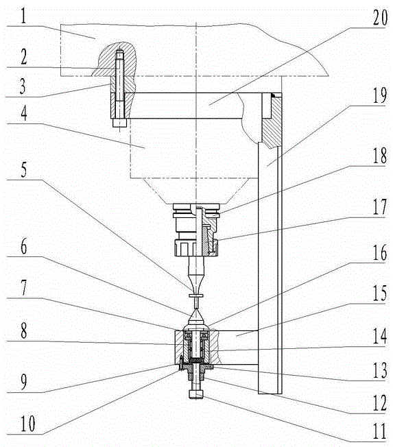
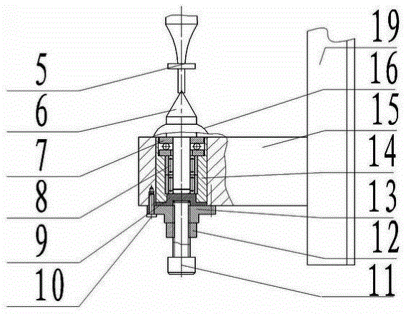
[0019] Such as figure 1 , figure 2 As shown, the milling cutter 5 is clamped on the spindle bearing seat 4 of the end milling head with a circlip 17 and a collet 18. Circular transition fit can play the role of pin hole positioning, ensuring the coaxiality accuracy of the center axis of the fixture and the spindle of the end milling head; Close on the bed 1 of the end milling head, the flange connecting sleeve 20 is welded on the fixed bracket 19, which ensures the firmness of the milling cutter installation, and ensures that the fixed bracket 19 is directly behind the CNC end milling machine table; the milling cutter 5 according to According to the needs of crankshaft processing, it is designed as a special milling cutter to ensure that it does not interfere with the journal of the crankshaft keyway when milling the keyway. When the milling cutter 5 is clamped by the circlip 17, there is a stepped shaft for positioning to ensure that the top 6 is tight. , the axial positio...


PUM


Abstract

A clamp for milling a crankshaft keyway in a numerical control mode is used for machining the crankshaft keyway through a numerical control machine tool. A milling cutter is clamped on a mainshaft bearing pedestal of a vertical milling head, the upper end face of a flange connecting sleeve is tightly pressed on the lathe bed of the vertical milling head without clearance, and the flange connecting sleeve is welded to a fixing support; a tip fixing plate of a lower end fixing device of the milling cutter is connected with the fixing support, a bearing sleeve is installed in the tip fixing plate, a thrust ball bearing is installed at the upper end of the bearing sleeve, an upper inner hole is closely matched with a tip, the lower end face is pressed on a circular bead of the bearing sleeve, a lower inner hole of the thrust ball bearing is in clearance fit with the tip, and an outer circle is matched with an inner hole of the bearing sleeve; a needle bearing is installed in the bearing sleeve, an outer circle of a small step of a pushing plate is in clearance fit with an inner circle of the bearing sleeve, the end face of the pushing plate is tightly pressed against the bearing sleeve, a bolt guiding plate is fixed to the tip fixing plate, and a hex socket cylindrical bolt is connected in the bolt guiding plate in a screwed mode; a leather ring is installed on the tip. The clamp is high in machining accuracy and efficiency, stable in machining quality, low in production cost and labor intensity and good in production environment and machining flexibility.

Description

technical field [0001] The invention relates to the technical field of mechanical manufacturing, in particular to a milling fixture for machining crankshaft key grooves by using a numerical control machine tool. Background technique [0002] The milling of the engine crankshaft keyway is a key item in the crankshaft machining process, and the technical requirements for the keyway are quite complicated and strict. The new technology of machining crankshaft keyway by CNC machine tool has never appeared in the same industry. At present, most domestic crankshaft manufacturers still use ordinary horizontal milling machines to process crankshaft keyways, but there are the following defects. [0003] 1. It is difficult to guarantee the machining accuracy with ordinary milling machines, and the machining quality is unstable. It is not suitable for the machining of semicircular keyways of batch and multi-variety crankshafts, and has poor adaptability. [0004] 2. Low production eff...

Claims


Application Information

Patent Timeline
Patent Type & Authority Patents(China)
IPC IPC(8): B23Q3/00
CPCB23Q3/00B23Q2703/105
Inventor 康笃玲裴志勇
Owner XIANGYANG FUDA DONGKANG CRANKSHAFT
Learn More