Rare earth permanent magnetic alloy continuous sintering equipment
A technology of sintering equipment and rare earth permanent magnets, which is applied in the field of permanent magnet alloy processing equipment and technology
- Summary
- Abstract
- Description
- Claims
- Application Information
AI Technical Summary
Problems solved by technology
Method used
Image
Examples
Embodiment 1
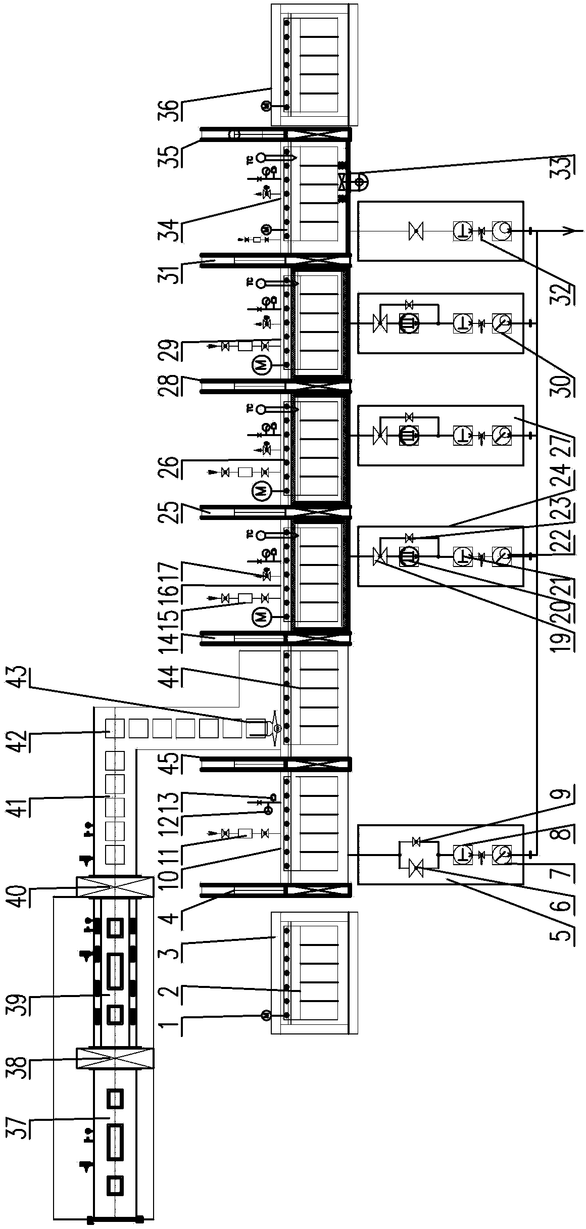
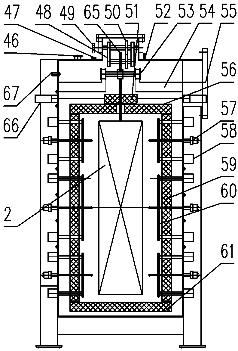
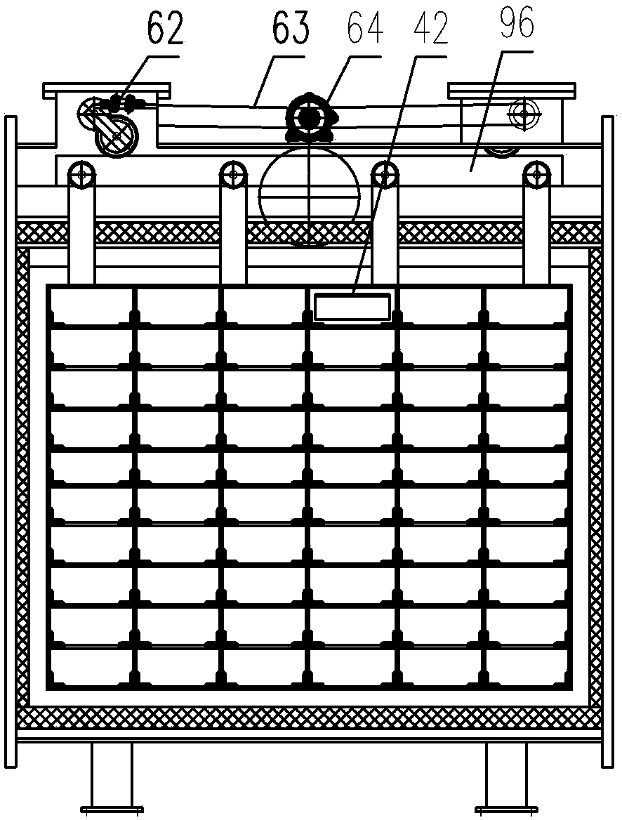
[0030] Embodiment 1: as figure 1As shown, the rare earth permanent magnet alloy continuous sintering equipment of the present invention consists of a preparation box 37, a glove box 39, and a sealed transfer box 41 arranged in sequence, and a lock chamber 10, a charging chamber 44, a preheating chamber 16, and a heating chamber arranged in sequence. The degassing chamber 26, the sintering chamber 29, the cooling chamber 34, the transmission device of each chamber, the return frame and the vacuuming device of each chamber are composed. Each chamber is connected by an isolation valve between chambers. Connection; the transmission device of each room is set on the upper part of each room, and the return frame with the transmission device is installed outside each room, and the transmission device of each room, the return frame and the transmission device on it together form a suspended conveying system 1; the return line The frame is connected with the transition frames 3, 36 at...
Embodiment 2
[0065] Embodiment 2: The mechanical structure of this example is the same as that of Example 1, the difference is: the limitation of parameters in the sintering process of this example, specifically:
[0066] (1) The compressed rare earth permanent magnet powder alloy billet is packaged in an air-isolated manner, and sent to the preparation box 37, the box door 90 is closed, and the air in the box is evacuated or filled with an inert gas; when the preparation box 37 and the glove box 39 Open the 6# isolation valve 38 between the boxes, transfer the packaged blanks to the glove box 39, close the 6# isolation valve 38 between the boxes; put the blanks into the material box 42 in the glove box 39, and the material box 42 yards are arranged stack; when the pressure balance of the glove box 39 and the sealed transfer box 41, open the 7# isolation valve 40 between the boxes, and transfer the stacked material boxes 42 to the sealed transfer box 41, and close the 7# isolation valve 40 ...
Embodiment 3
[0074] Embodiment 3: The difference between this example and Example 2 is: the limitation of parameters in the sintering process of this example, specifically:
[0075] In step (2), when the pressure in the charging chamber 44 and the preheating chamber 16 is balanced, open the 1# isolation valve 14 between the chambers, transfer the rack 2 to the preheating chamber 16, close the 1# isolation valve 14; start vacuuming, When the vacuum degree is higher than 1Pa, start heating to 500°C and keep it warm for 1 hour;
[0076] Step (3), the heating and degassing chamber 26 is in a vacuum state, the heating temperature is 500°C, open the 2# isolation valve 25 in the room, transfer the material rack 2 to the heating and degassing chamber 26, close the 2# isolation valve 25; The temperature is raised from 500°C to 850°C in multiple stages and kept warm for 4 hours, and the vacuum degree reaches 3E-2Pa.
PUM
 Abstract
Description
Claims
Application Information
 - R&D
- Intellectual Property
- Life Sciences
- Materials
- Tech Scout
- Unparalleled Data Quality
- Higher Quality Content
- 60% Fewer Hallucinations
Browse by: Latest US Patents, China's latest patents, Technical Efficacy Thesaurus, Application Domain, Technology Topic, Popular Technical Reports.
© 2025 PatSnap. All rights reserved.Legal|Privacy policy|Modern Slavery Act Transparency Statement|Sitemap|About US| Contact US: help@patsnap.com


