Method and apparatus for inhibiting ice accumulation in HVAC systems

Inactive Publication Date: 2005-12-06
WIGGS B RYLAND
View PDF9 Cites 44 Cited by
  • Summary
  • Abstract
  • Description
  • Claims
  • Application Information

AI Technical Summary

Benefits of technology

[0009]This objective is accomplished by means of applying a non-stick coating to the exterior portion of any refrigerant-based or evaporative cooling based heating or cooling system where undesirable ice accumulation could occur. The non-stick coating will prevent ice from adhering to the exterior finned heat transfer tubing, or to any other air-exposed system surface areas desired. In turn, this will provide advantages such as eliminating the need for a defrost or a de-icing cycle, increasing system operational efficiencies, and decreasing system operational costs.
[0012]While the operation of an electric fan alone may blow away any thin film of humidity induced condensation ice, or other form of frozen water, which has not fallen by operation of gravity, from the non-stick exterior air heat exchange coils of a conventional air-source heat pump when operating in the heating mode in the winter, a problem with ice removal could still exist if the fins, for expanded air surface contact connected to the refrigerant conductive tubing, are too closely spaced or are horizontally oriented. To achieve a more reliable ice removal method, in conjunction with the non-stick surface coating, a fin design should be utilized whereby the fins are sloped, or are spiraled, downwardly, or are in a vertical position such that the fins extend in a substantially parallel direction to the longitudinal axis of the tubes transporting the refrigerant fluid, so that gravity alone will pull off any ice forming on the non-stick surface.
[0014]The exterior non-stick coated air heat exchange unit must be sufficiently elevated so as to allow falling ice to accumulate underneath the unit without building up from below so as to hamper the heat exchange ability of the refrigerant system. Further, the exterior unit should be furnished with a non-stick coated downwardly sloped base, cone-shaped base, or the like, so falling ice will slide harmlessly to the side, at a sufficient distance away from the unit to avoid any airflow obstruction or any other decrease in system operational efficiencies. Additionally, the exterior unit may be equipped with an optional vibrator, which may be programmed to periodically vibrate the finned heat exchange tubing as appropriate, to further enhance the ability of the non-stick surface coating to remove any ice, or other frozen moisture, build-up. The electrical power required to periodically operate a relatively small vibrator is significantly less than the power required by a conventional defrost cycle.

Problems solved by technology

However, when typical air-source heat pump systems are operating in the heating mode, since the refrigerant fluid, which is being circulated into the exterior outdoor heat exchange unit exposed to the air, is typically below the freezing point of water, as the exterior air temperature approaches, or falls below, the freezing point of water, humidity in the air collects on the finned tubing and is frozen.
This freezing humidity gradually builds up ice accumulations to the extent that it blocks the airflow designed to pass over the finned tubing, thereby rendering the system unable to acquire sufficient heat from the air to operate at design levels.
This periodic defrost cycle results in excessive wear and tear on the compressor, tending to shorten compressor life, as well as in lowered system efficiencies and higher operational costs.
Similarly, in large commercial evaporative cooling chillers, which must periodically operate in below freezing temperatures, and which sometimes must operate with a cooling load significantly less than called for by system design, the water utilized for evaporative cooling on the exterior of the heat transfer tubing may freeze.

Method used


Image

  • Method and apparatus for inhibiting ice accumulation in HVAC systems
  • Method and apparatus for inhibiting ice accumulation in HVAC systems

Examples


Embodiment Construction

[0021]A method and apparatus for inhibiting condensation ice accumulation on heat transfer systems, including refrigerant-based heating and cooling systems, and on an evaporative cooling system, according to the invention, utilizes a non-stick coating applied to heat exchange components and other exterior surface areas of the refrigeration system where ice accumulation is not desirable because such ice decreases overall system operational efficiencies. Additionally, according to the invention, a certain design for outdoor air heat exchange means, and an optional vibrator, enhance the ability to eliminate condensation ice build-up.

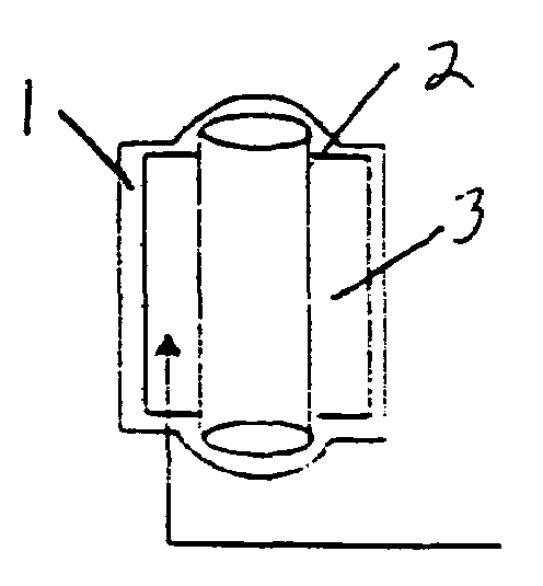
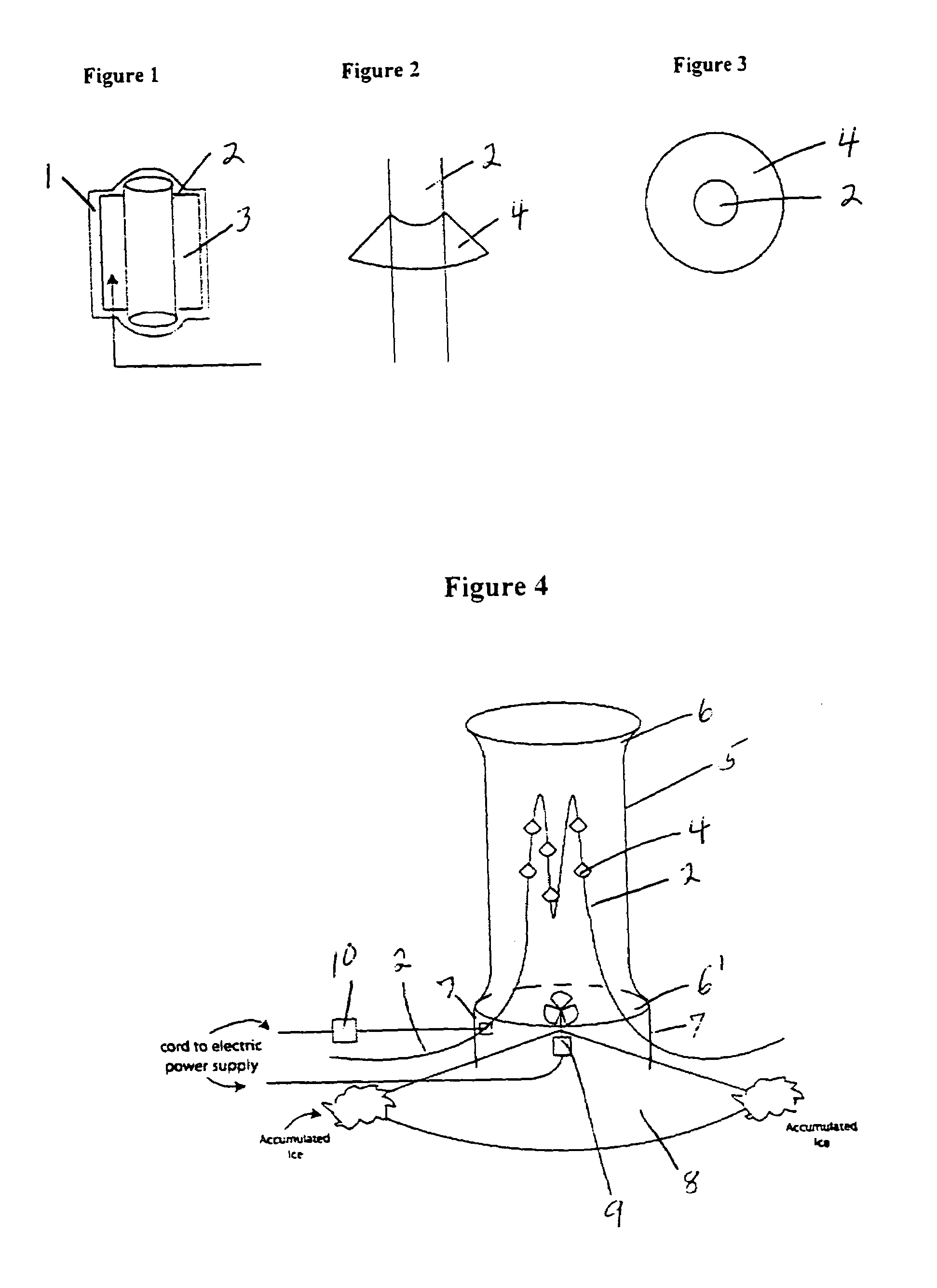
[0022]In one embodiment of the invention, as shown via a side view in FIG. 1, not drawn to scale, a heat exchange component of a heat transfer system is shown. The heat exchange component is a segment of fluid (such as refrigerant fluid) transport tubing 2 with two exterior expanded surface area heat transfer fins 3 in thermal contact with, and arranged in ...


PUM


Abstract

A non-stick coating, which inhibits frozen moisture accumulation, is applied to exterior exposed portions of heating and cooling systems where ice or other frozen moisture can accumulate and impair system design operational efficiencies; where heat exchange tubing and fins are downwardly sloped or angled; with an optional protective shell encasement which can be shaped to provide a vena contracta effect; with an optional electric fan to enhance airflow for heat exchange; with an optional electric vibrator to enhance inhibition of frozen moisture accumulation; with a downwardly sloped base to direct falling frozen moisture away from the heat exchange equipment; for use in conjunction with an air source heat pump system, an evaporative cooling system or a chiller, or as a supplement to a water-source heat pump system or to a direct expansion heat pump system; and for use with any other refrigerant-based heating system or cooling system.

Description

[0001]A portion of the disclosure of this patent document contains material that is subject to copyright protection. The copyright owner has no objection to the facsimile reproduction by anyone of the patent document or the patent disclosure, as it appears in the Patent and Trademark office patent file or records, but otherwise reserves all copyright rights whatsoever.BACKGROUND OF THE INVENTION[0002]The invention relates to the field of refrigerant-based heating and cooling systems, and to evaporative cooling systems, and more particularly to a system designed to inhibit condensation or other frozen moisture accumulation on heat exchange equipment or tubing, which tubing is typically finned, and which equipment or tubing is exposed to the air, by means of the application of a non-stick coating to the exterior portion of such air-exposed equipment or tubing, or finned tubing, or the like.[0003]Virtually all heating and cooling systems utilize equipment or a heat exchange means which...

Claims


Application Information

Patent Timeline
IPC IPC(8): F25D21/00F25D21/04F28F19/00
CPCF25D21/04F28F19/006
Inventor WIGGS, B. RYLAND
Owner WIGGS B RYLAND
Why Eureka
Try Eureka