
Electromagnetic actuator, and electromagnetic clutch and differential using the same

a technology of electromagnetic clutch and differential, which is applied in the direction of magnets, magnetic bodies, gearing, etc., can solve the problems of shortening the actuation force, failing to engage, increasing current consumption and heat generation, etc., and achieves the effect of preventing the system from being enlarged and suppressing power consumption and heat generation

Active Publication Date: 2008-02-05
TOCHIGI FUJI IND CO LTD
View PDF14 Cites 47 Cited by
  • Summary
  • Abstract
  • Description
  • Claims
  • Application Information

AI Technical Summary

Benefits of technology

[0012]The invention is directed to an electromagnetic actuator, and an electromagnetic clutch and a differential using the same that securely actuate the clutch system and suppress power consumption and heat generation, thus preventing the system from being enlarged. This electromagnetic clutch actuator actuates the clutch system for limiting differential under actuation force due to the electromagnet, and a detector precisely detects the substance of actuation in the clutch system.
[0014]For preventing shortage of the actuation force, the excitation current does not need to keep being supplied to the electromagnetic coil. This prevents current consumption and heat generation from increasing and does not need normal supplying of excitation current. This prevents the electromagnet and system using the same from being enlarged to reduce solenoid current (or excitation current), thus preventing layout and vehicle mountability from being deteriorated.
[0015]The excitation current is applied to the electromagnetic coil when the clutch is actuated, and, thereafter, is reduced to the hold current at a necessary timing. This allows for setting to a higher excitation current, thus allowing for a smaller and lighter electromagnet.

Problems solved by technology

This prediction causes a shortage of the actuation force, thus failing to engage the engagement clutch.
For preventing the shortage of the actuation force, however, the electromagnetic solenoid requires normal supplying of the excitation current, which increases current consumption and heat generation.
This renders the system larger, and deteriorates the layout and vehicle mountability.

Method used


Image

  • Electromagnetic actuator, and electromagnetic clutch and differential using the same
  • Electromagnetic actuator, and electromagnetic clutch and differential using the same
  • Electromagnetic actuator, and electromagnetic clutch and differential using the same

Examples


Embodiment Construction

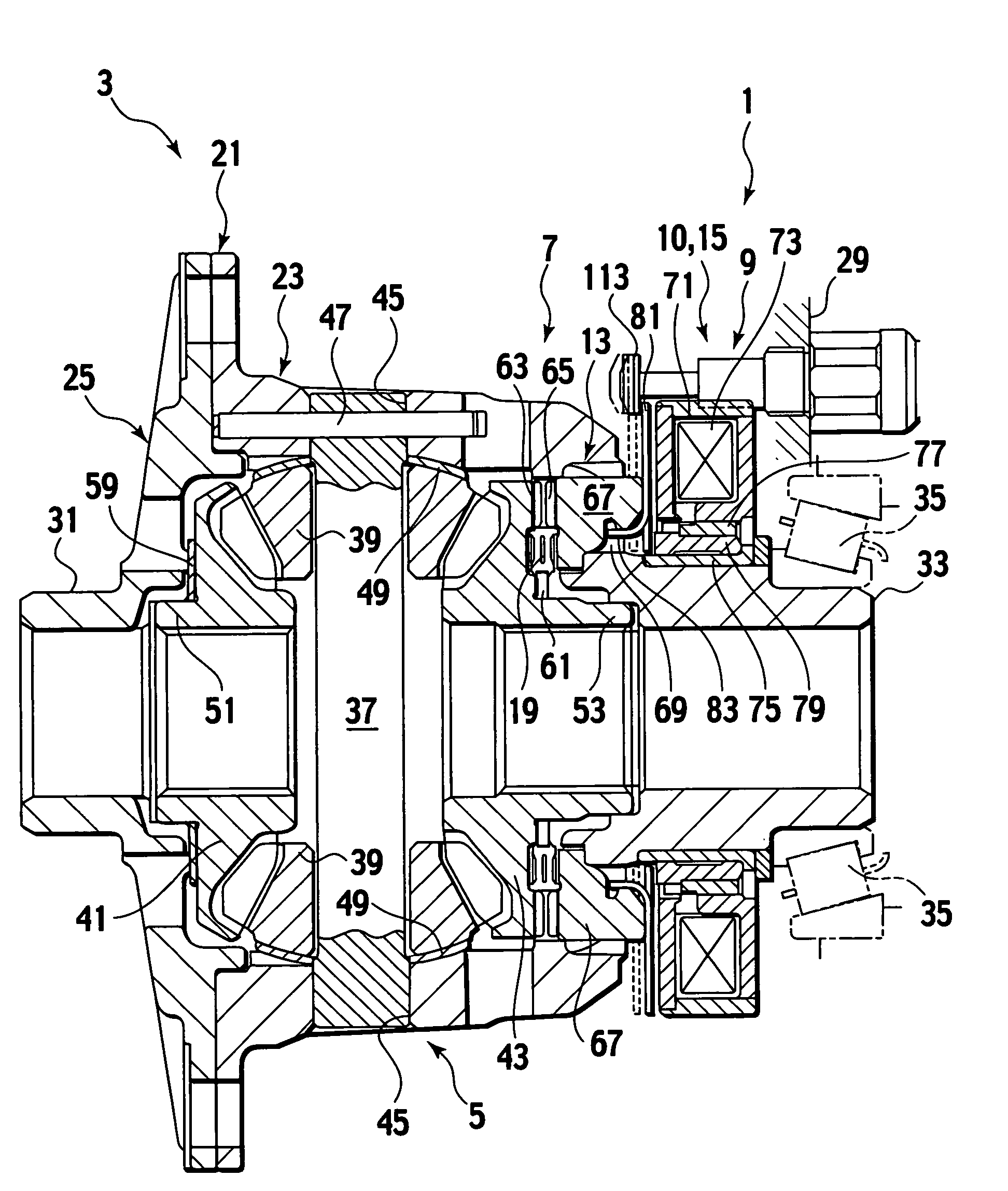
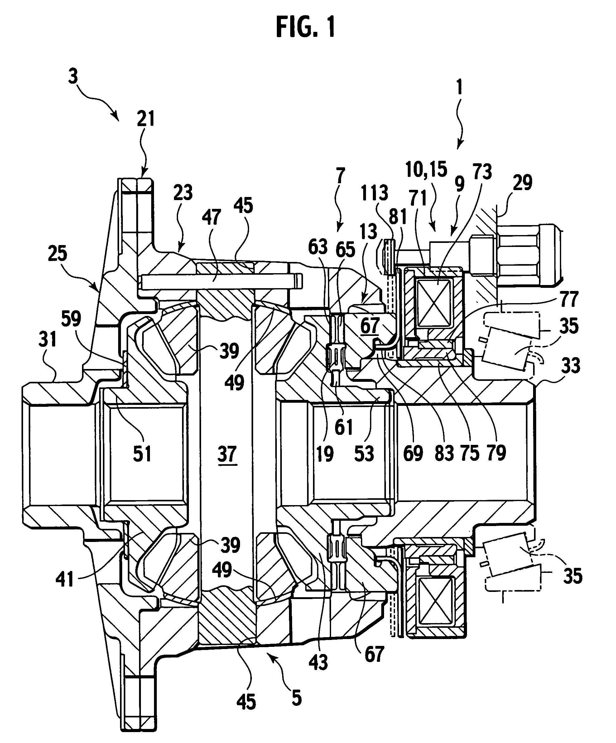
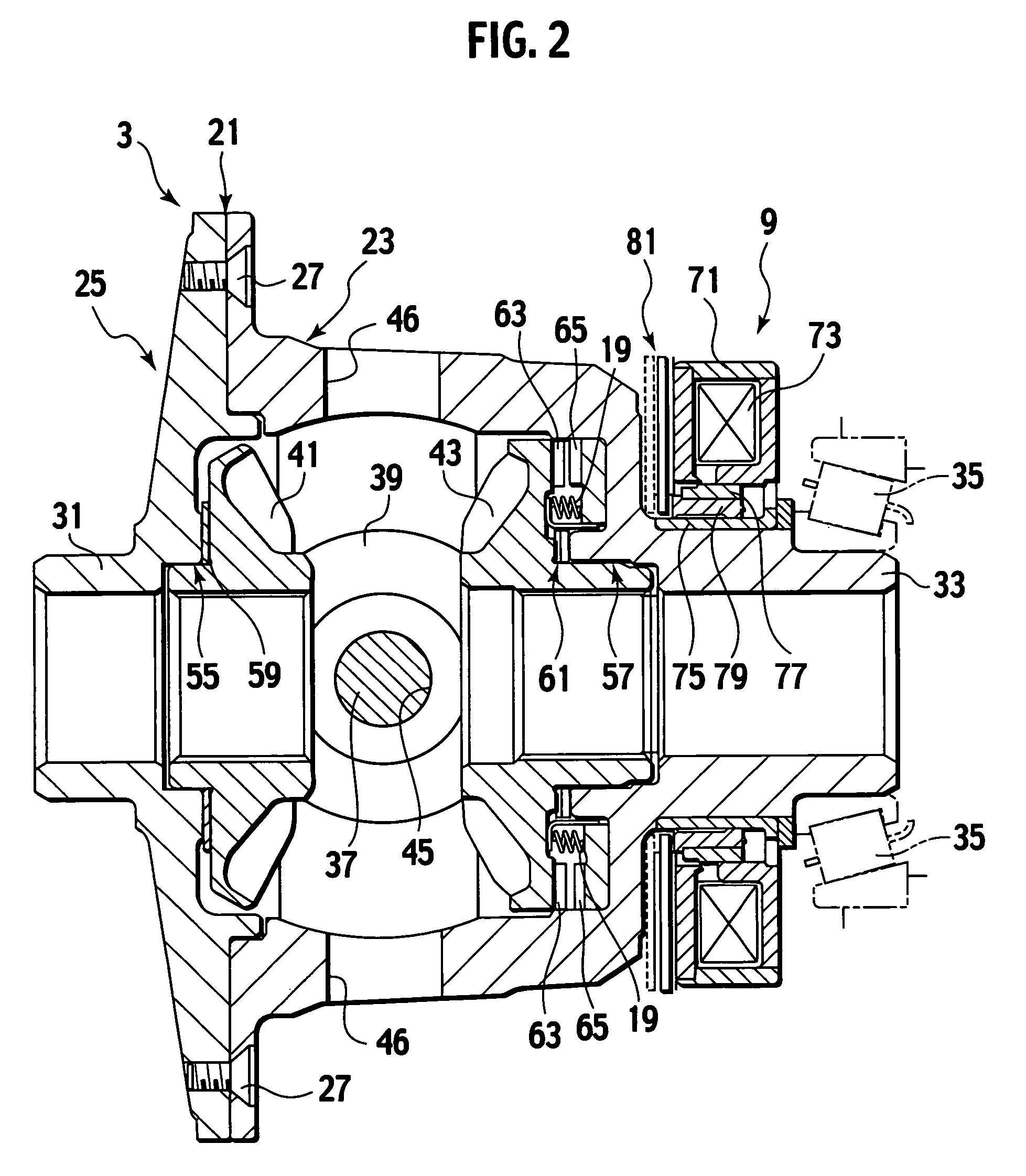
[0036]An embodiment of the invention will hereby be described as the following with reference to FIGS. 1 to 5.

[0037]An electromagnetic actuator 1 (or an embodiment of the invention), and an electromagnetic clutch and a differential 3 employing the electromagnetic actuator 1. In the following description, the left and right direction indicates the left and right direction of a vehicle employing the differential 3 or in FIG. 1.

[0038]The electromagnetic actuator 1 is described.

[0039]With reference to FIG. 1, the electromagnetic actuator includes a differential-lock electromagnet 9 (referred to as an electromagnet) that provides actuation force according to a solenoid current to a dog clutch 7 as a clutch for actuation that locks differential mechanism 5 with differential rotation.

[0040]The differential mechanism 5 adopts a bevel gear mechanism as one means. The electromagnetic actuator 1 includes a detector 10 that detects the dog clutch 7 actuated to generate a detection signal (or de...


PUM

PropertyMeasurementUnit
actuation forceaaaaaaaaaa
currentaaaaaaaaaa
hold currentaaaaaaaaaa

Abstract

The electromagnetic actuator includes an electromagnetic coil configured to provide actuation force in accordance with a solenoid current to be supplied, to a clutch and configured to actuate the clutch to control relative rotation between first and second members. The electromagnetic actuator includes a detector configured to detect the clutch actuated to produce a detection signal. The electromagnetic actuator includes a controller configured to respond to the detection signal from the detector to control the solenoid current.

Description

CROSS-REFERENCE TO RELATED APPLICATIONS[0001]This application is based upon and claims the benefit of priority from Japanese Patent Application No. 2004-178493 filed on Jun. 16, 2004; the entire contents of which are incorporated herein by reference.BACKGROUND OF THE INVENTION[0002]1. Field of the Invention[0003]The invention relates to an electromagnetic actuator for locking or releasing relative rotation between relative rotation members and an electromagnetic clutch using the same, and, specifically, a differential using the electromagnetic clutch.[0004]2. Description of Relevant Art[0005]The patent application publication laid-open No.Hei11-186031 as a relevant document describes “a method of actuating a solenoid and an actuator”.[0006]When a general electromagnetic actuator actuates, for example, an engagement clutch (clutch system), firstly a large solenoid current is supplied to an electromagnetic solenoid. This allows the electromagnet to be excited, thus engaging the engage...

Claims


Application Information

Patent Timeline
Patent Type & Authority Patents(United States)
IPC IPC(8): F16D27/108F16H48/24B41J2/32F16D27/118H01F7/18
CPCF16D27/118F16H48/08F16H48/24F16D2500/1022F16D2500/10425F16D2500/10462F16D2500/30401F16D2500/70418F16H2048/346H01F7/1844
Inventor FUSEGI, MASAAKI
Owner TOCHIGI FUJI IND CO LTD
Learn More