Power consumption control circuit, intelligent power module and frequency variable household appliance
A technology for power consumption control and control module, which is applied in the direction of converting DC power input to DC power output, adjusting electrical variables, and controlling/regulating systems, etc. The problem of low switching loss of components, etc., achieves the effect of reducing the occupied area, small driving capacity, and reducing power consumption
- Summary
- Abstract
- Description
- Claims
- Application Information
AI Technical Summary
Problems solved by technology
Method used
Image
Examples
Embodiment 1
[0096] Embodiment 1: The switching control module 306 only makes any one of the IGBT tubes in the working state when receiving the first signal.
[0097] (1) Module composition
[0098] corresponds to Figure 4 The intelligent power module shown, Figure 5 A schematic structural diagram of a power consumption control circuit according to an embodiment of the present invention is shown.
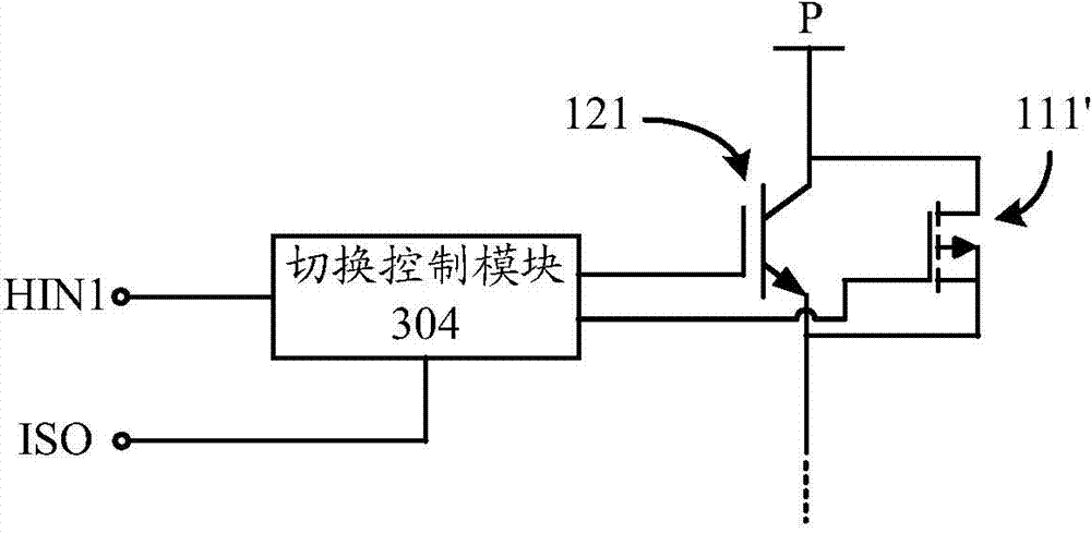
[0099] like Figure 5 As shown, according to an embodiment of the present invention, preferably, the switch control module 304 may include: a switch circuit 3042, and an NMOS transistor is used as an example for illustration in the figure, and the gate of the NMOS transistor is connected to the control chip through the ISO port, the drain The electrode is connected to the current signal source, the substrate is connected to the source and grounded, and is used to conduct when the high-frequency operating signal is received, so that the signal source is grounded, and when the low-frequency o...
Embodiment approach 1
[0103] Figure 6A Yes Figure 5 A schematic structural view of a specific implementation of the illustrated embodiment.
[0104] like Figure 6A As shown, according to a preferred embodiment of the present invention, the state control circuit 3044 includes: an analog switch, and the analog switch includes: a control element connected to the signal source (such as the above-mentioned current signal source) and the Between the switch circuits 3042, a first switch signal is generated when the switch circuit 3042 is turned on, and a second switch signal is generated when the switch circuit 3042 is turned off; controlled, one end of the controlled is connected to the corresponding signal input terminal of the switch component (such as Figure 6A The HIN1 port shown), the other end of the controlled device is connected to the first driving circuit 4409 when receiving the first switching signal, and connected to the second driving circuit 4409 when receiving the second switching s...
Embodiment approach 2
[0108] Figure 6B Yes Figure 5 A schematic structural view of another embodiment of the illustrated embodiment.
PUM
 Abstract
Description
Claims
Application Information
 - R&D
- Intellectual Property
- Life Sciences
- Materials
- Tech Scout
- Unparalleled Data Quality
- Higher Quality Content
- 60% Fewer Hallucinations
Browse by: Latest US Patents, China's latest patents, Technical Efficacy Thesaurus, Application Domain, Technology Topic, Popular Technical Reports.
© 2025 PatSnap. All rights reserved.Legal|Privacy policy|Modern Slavery Act Transparency Statement|Sitemap|About US| Contact US: help@patsnap.com


