
Faraday apparatus for measuring beam

A measuring device, Faraday cup technology, applied in the direction of measuring device, radiation measurement, X/γ/cosmic radiation measurement, etc., can solve problems such as difficult to guarantee sealing performance, heat generation, inaccurate test results, etc., and achieve magnetic circuit design Reasonable, simple wiring, good cooling effect

Active Publication Date: 2014-05-14
BEIJING SHUOKE ZHONGKEXIN ELECTRONICS EQUIP CO LTD
View PDF4 Cites 22 Cited by
  • Summary
  • Abstract
  • Description
  • Claims
  • Application Information

AI Technical Summary

Problems solved by technology

It proposes a good solution to the inaccuracy of the test results of the existing beam Faraday measurement device, the difficulty in ensuring the sealing performance and the heating phenomenon

Method used


Image

  • Faraday apparatus for measuring beam
  • Faraday apparatus for measuring beam
  • Faraday apparatus for measuring beam

Examples

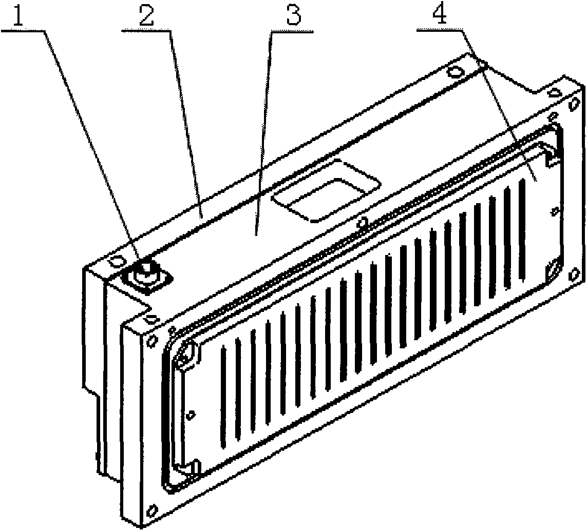
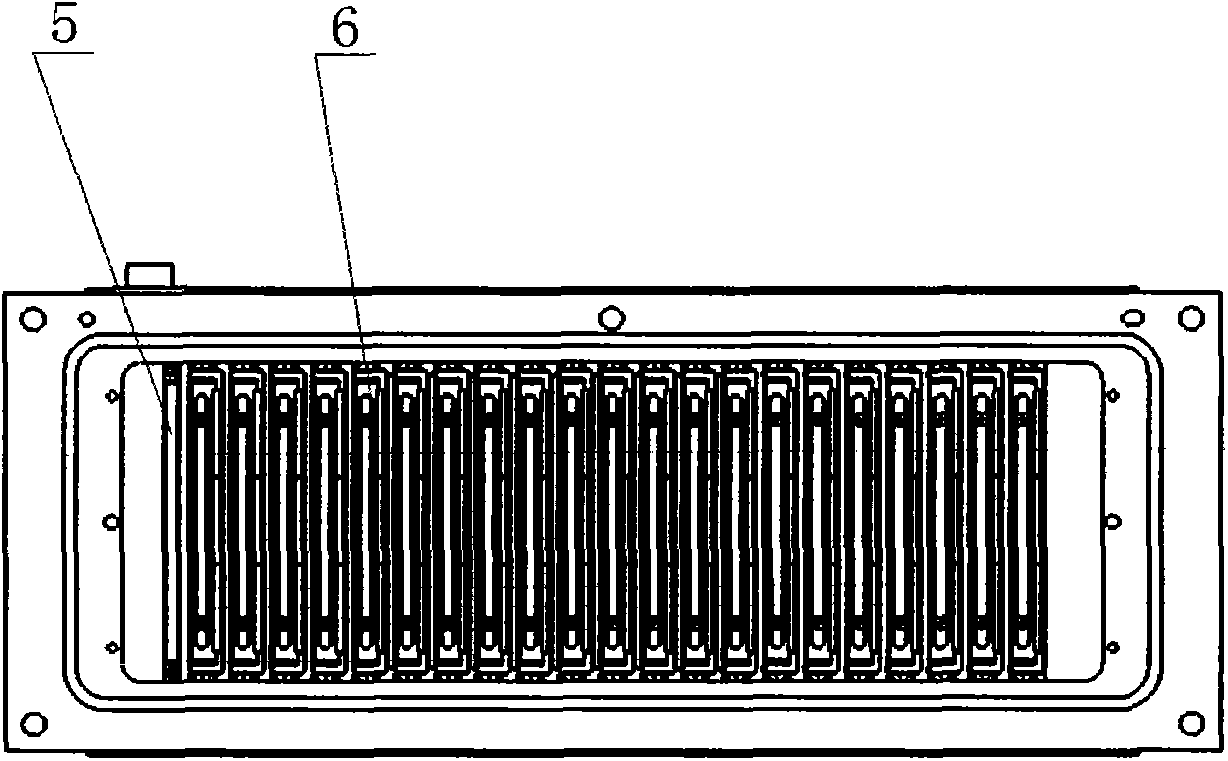
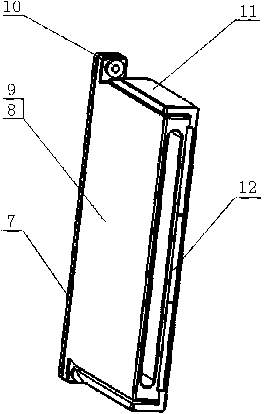

Embodiment Construction

[0023] Attached below figure 1 , attached figure 2 And attached image 3 The present invention is further introduced, but not as a limitation to the present invention. The scope of the invention is limited only by the scope of the appended claims.

[0024] One embodiment of the present invention is as figure 1 , figure 2 and image 3 shown.

[0025] see figure 1 , figure 2 and image 3 , a beam Faraday measuring device, comprising: a sealed socket (1), a Faraday cup mounting plate (2), a Faraday collection frame (3), a graphite baffle (4), a magnetic plate (5), a miniature Faraday cup (6), where if image 3 As shown, the miniature Faraday cup (6) is composed of an insulating gasket (7), a Faraday cup body (8), graphite at the bottom of the cup (9), a small insulating gasket (10), a magnet mounting plate (11) and a suppression magnet (12). A total of 21 of the miniature Faraday cups (6) are installed side by side with the magnetic guide plate (5) on the Faraday c...


PUM


Abstract

The invention discloses a Faraday measurement apparatus for beam. The apparatus comprises a sealing socket (1), a Faraday cup mounting plate (2), a Faraday collection frame (3), a graphite baffle plate (4), a magnetic conductive plate (5), and micro Faraday cups (6). The micro Faraday cups (6) are installed at the Faraday cup mounting plate (2); the Faraday cup mounting plate (2) is fixed at an ion implanter based on connection of the Faraday collection frame (3); and the graphite baffle plate (4) is installed at the Faraday collection frame (3) and is located at a front position at the inlets of the micro Faraday cups (6). The apparatus is characterized in that 21 micro Faraday cups (6) are arranged and the 21 micro Faraday cups (6) and the magnetic conductive plate (5) are installed at the Faraday cup mounting plate (2) in parallel in a vacuum environment; the currents of the Faraday cup mounting plate (2) are led out by the sealing socket (1); and the sealing socket (1) is fixed at the position, approaching the Faraday cup mounting plate (2), of the Faraday collection frame (3). According to the invention, the beam measurement angle is accurate; the sealing performance influence on the vacuum system by the apparatus is low; and the generated heat is low. The invention relates to an ion injection device which belongs to the semiconductor manufacturing field.

Description

technical field [0001] The invention relates to a semiconductor device manufacturing control system, that is, an ion implanter, and particularly relates to a beam current measurement device for the ion implanter. Background technique [0002] With the development of semiconductor technology, the uniformity and stability of the beam is becoming more and more important to the ion implantation system, which has a great impact on the quality of implanted products and the industrialization of ion implanters. The control of beam uniformity and stability must be supported by beam measurement parameters. When the ion beam current is established and optimally adjusted, the beam distribution is detected in real time, the parallel beam parameters are detected before implantation, and the implanted dose is detected in real time during implantation. These parameters are all completed by different beam measurement Faradays. [0003] Good uniformity is the basis for finally obtaining high...

Claims


Application Information

Patent Timeline
Patent Type & Authority Applications(China)
IPC IPC(8): G01T1/29
Inventor 庞云玲
Owner BEIJING SHUOKE ZHONGKEXIN ELECTRONICS EQUIP CO LTD
Learn More