
Thermal treatment device of field joint of steel containment of nuclear power plant and thermal treatment method

A steel containment and heat treatment device technology, applied in heat treatment furnaces, heat treatment equipment, manufacturing tools, etc., can solve the problem of inability to achieve uniform distribution and constant heat treatment temperature, inability to closely fit insulation cotton and heating block, and poor heat treatment quality No problems such as guarantee, to achieve the effect of improving the construction efficiency of heat treatment, strengthening the effect of heat conduction and heat preservation, and improving the quality of heat treatment

Active Publication Date: 2015-05-13
CHINA NUCLEAR IND HUAXING CONSTR
View PDF5 Cites 0 Cited by
  • Summary
  • Abstract
  • Description
  • Claims
  • Application Information

AI Technical Summary

Problems solved by technology

[0005] 1. The flame baking method is cyclical localized centralized heating. Under the objective conditions of large heat dissipation area, the heat treatment of the weld seam using this method cannot achieve uniform distribution and constant heat treatment temperature in the length of the weld seam and thickness direction, and the quality of heat treatment can be improved. There is no guarantee, and it takes a long time to bake to the specified temperature, and consumes a lot of combustible gas
[0006] 2. The simple supporting electric heating method is to repeatedly support and fix the heating block on the weld seam and lay insulation cotton on the heating block. There is a greater risk in quality and low construction efficiency

Method used


Image

  • Thermal treatment device of field joint of steel containment of nuclear power plant and thermal treatment method
  • Thermal treatment device of field joint of steel containment of nuclear power plant and thermal treatment method
  • Thermal treatment device of field joint of steel containment of nuclear power plant and thermal treatment method

Examples


Embodiment Construction

[0040] Preferred embodiments of the present invention will be described below with reference to the accompanying drawings.

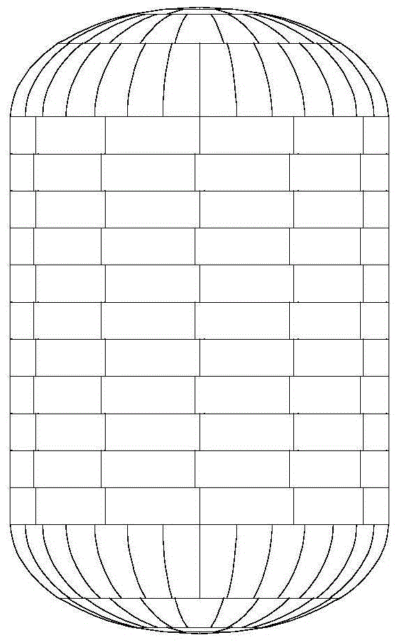
[0041] like figure 1 As shown, the nuclear power plant steel containment vessel (CV) in this embodiment includes three parts: a spherical bottom head, a cylindrical body and a spherical top head, with a diameter of 39.6m. Among them, the bottom head and the top head are tailor-welded from a total of 64 hyperboloid high-strength and tough SA738Gr.B steel plates. The cylinder body is composed of 11 rings of wall panels, each ring is made of 12 single-curved high-strength and tough SA738Gr.B steel plates, including 132 vertical welds (also known as longitudinal seams) and 12 circular seams. All welds need to be preheated before welding, and some welds need stress relief heat treatment after welding.

[0042] The pre-weld preheating treatment of the installation weld seam of the steel containment of the nuclear power plant in this embodiment adopts figur...


PUM


Abstract

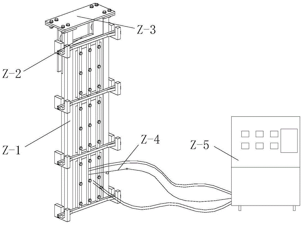
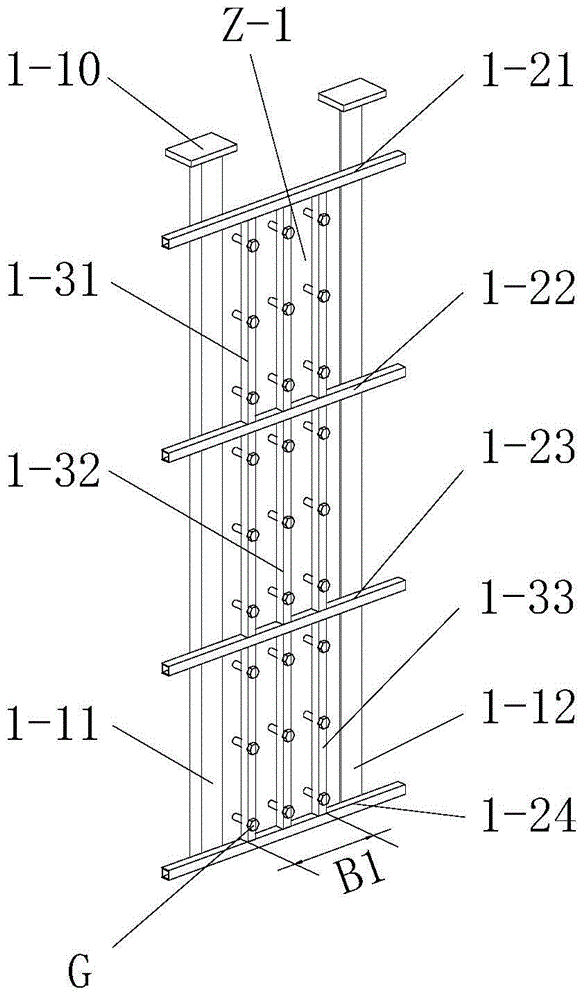
The invention relates to a thermal treatment device of a field joint of a steel containment of a nuclear power plant and a thermal treatment method, belonging to the technical field of construction of the nuclear power plant. The device mainly consists of a main framework (Z-1), heating insulators (Z-2), a traveling mechanism (Z-3), a temperature sensing apparatus (Z-4) and an automatic temperature controller (Z-5). During thermal treatment, the traveling mechanism of the thermal treatment device is supported at the upper edge of a wall plate of the containment and is moved along the upper edge, so that the heating insulators on both sides of the wall plate of the containment are located in a position for clamping the to-be-thermally-treated joint. Then, the temperature sensor is installed at the to-be-thermally-treated joint. After an electric heating apparatus is connected, under the closed loop control of the automatic temperature controller, the joint is heated to a predetermined temperature. According to the invention, the insulating cotton, the electric heating apparatus and the joint are compactly attached, and the joint quality is remarkably improved and the welding period is remarkably shortened by guaranteeing the thermal treatment quality and efficiency.

Description

technical field [0001] The invention relates to a device for installation and welding of steel containment shells of nuclear power plants, in particular to a heat treatment device for installation welds of steel containment shells of nuclear power plants, and provides corresponding heat treatment methods at the same time, belonging to the technical field of nuclear power plant construction. Background technique [0002] As an important part of the passive system, the containment vessel (CV) can effectively prevent the internal pressure of the containment from exceeding the design value and prevent the leakage of radioactive materials under accident conditions. It is one of the important equipment to ensure the safe operation of nuclear power. The steel containment vessel of AP1000 third-generation nuclear power plant is a hermetic steel container, including three parts: bottom head, cylinder body and top head. It is about 3400m, and the groove section is large. Compared with...

Claims


Application Information

Patent Timeline
Patent Type & Authority Patents(China)
IPC IPC(8): C21D9/50
Inventor 张科青费松陈宝智秦亚林别刚刚马富巧陈美丹
Owner CHINA NUCLEAR IND HUAXING CONSTR
Learn More