Combined facial expression simulation device

A technology of facial expressions and simulation devices, applied in manipulators, manufacturing tools, etc., can solve the problems of high cost, monotonous expressions, and difficult manipulation, and achieve the effects of low cost, improved environmental adaptability, and convenient mass production

Inactive Publication Date: 2014-05-07
NORTHWESTERN POLYTECHNICAL UNIV
View PDF14 Cites 7 Cited by
  • Summary
  • Abstract
  • Description
  • Claims
  • Application Information

AI Technical Summary

Problems solved by technology

[0003] In order to avoid the deficiencies of the existing technology and overcome the problems of complex mechanism, difficult manipulation, monotonous expression and high cost of the facial expression simulation robot, the present invention proposes a combined facial expression simulation device

Method used


Image

  • Combined facial expression simulation device
  • Combined facial expression simulation device
  • Combined facial expression simulation device

Examples


Embodiment 1

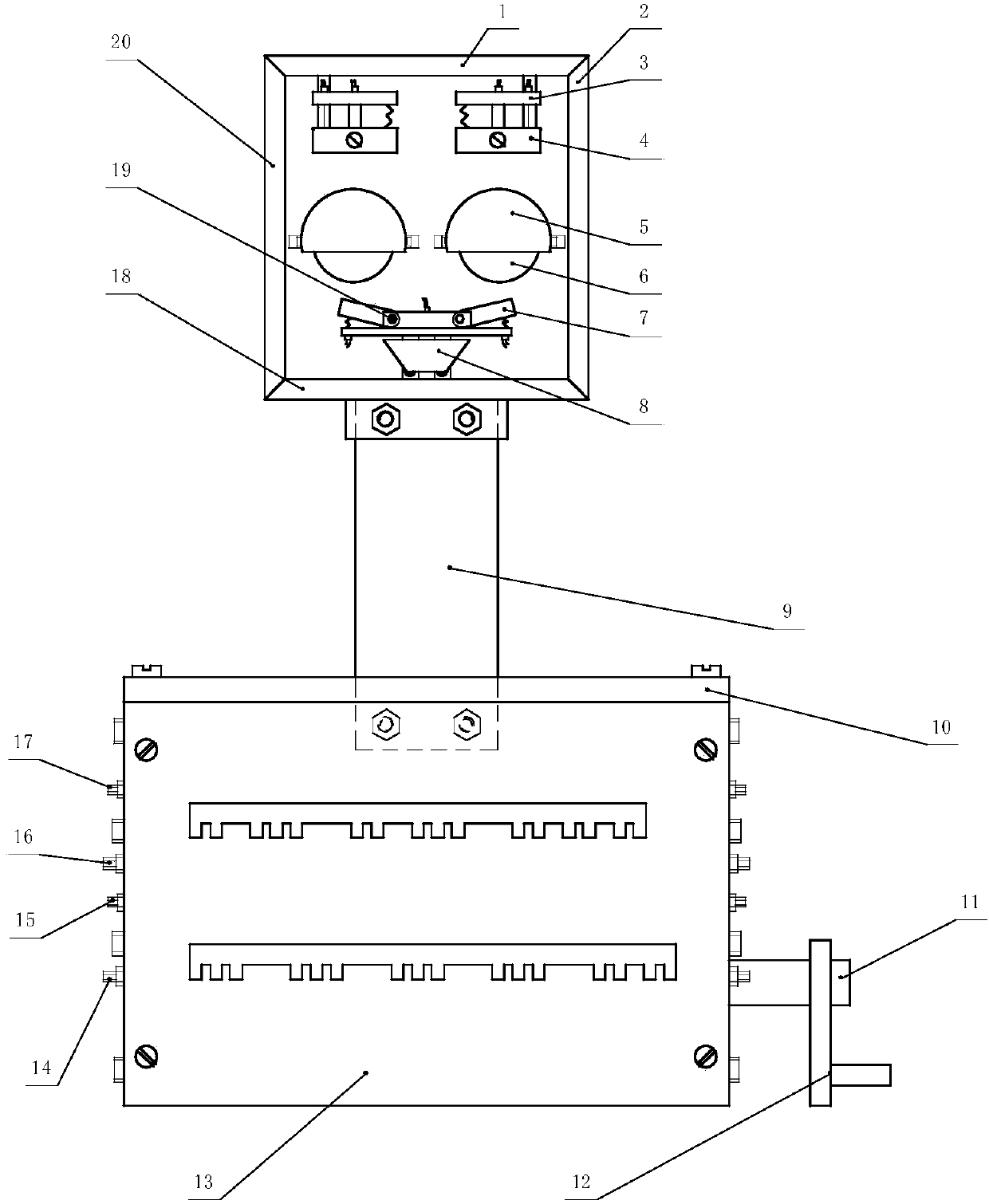
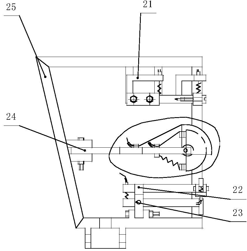
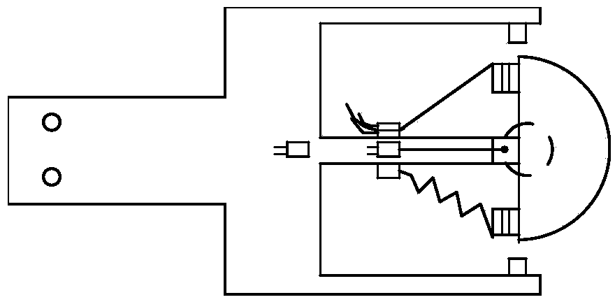
[0023] refer to Figure 1-Figure 8 , the combined facial expression simulation device of the present embodiment comprises a head mechanism, an intermediate connection bracket, and an operation box; Plate 20, head rear side plate 25, first fixed bracket 3, second fixed bracket 21, third fixed bracket 22, fourth fixed bracket 24, first pin shaft 19, second pin shaft 23, eyebrow assembly 4, Eyelid assembly 5, eyeball assembly 6, beard assembly 7, mouth assembly 8 and flexible tube, steel wire rope, spring are formed, head upper panel 1, head right side panel 2, head lower panel 18, head left side panel 20, The five panels of the head rear side plate 25 are glued to form the head frame structure; the eyebrow components 4 are respectively fixed on the head upper panel 1 by bolts, and the first fixing bracket 3 and the second fixing bracket 21 are fixedly connected by screws at one end. The eyebrow assembly 4 is connected with the second fixed bracket 21 other end by screws, the fl...

Embodiment 2

[0030] The operator lifts the front swing rod fixed shaft 14 and the rear swing rod fixed shaft 16, finds the corresponding shift fork 37, lifts the shift fork 37 upward, and then moves left and right to the predetermined position, driving the corresponding cam group 39 Move on the shaft, buckle the shift fork 37 to the shift fork placement groove provided on the control panel 13, then put down the front swing rod fixed shaft 14 and the rear swing rod fixed shaft 16 and fix them with nuts, shake the handle 12 to input power, The movement of each expression component forms another complete set of facial expressions. It is assumed that there are ai cams on each cam group, where i=1,2,3...13; 13 cam groups combine to form ∏ai expressions, where i=1,2,3. .....13; that is, to form rich facial expressions.


PUM


Abstract

The invention discloses a combined facial expression simulation device, wherein the classic mechanical transmission mode mainly dominated by a cam mechanism is adopted, the operating personnel only needs to rotate a handle to input power by virtue of a single-input and multiple-output structure, next, a main shaft and an auxiliary shaft drive a gear, a cam and a connecting rod assembly to move, and furthermore, a cam assembly is driven to move and then an oscillating bar moves along with the cam assembly, and then a steel wire rope is pulled to drive each expression execution mechanism to move, and therefore, a complete facial expression is formed; the steel wire rope is guided by a flexible pipe which can be bent arbitrarily without affecting sliding of the steel wire rope therein, and as a result, the whole system is enabled to be more stable in transmission and simple in structure. For switching expressions, a corresponding shifting fork is applied to shifting so that a corresponding cam group can move from side to side on a shaft to a predetermined position, the shifting fork is locked in a square groove and then the handle is rotated to input power, and finally, another new facial expression is formed by the expression simulation device; the combined facial expression simulation device is convenient to operate and control. The surface components are all designed to be modularized and convenient for batch production.

Description

technical field [0001] The invention relates to a mechanically manipulated simulation device, in particular to a combined facial expression simulation device. Background technique [0002] Most of the existing domestic robot simulation technologies are based on experimental research and software simulation, and the simulation of facial expressions cannot be fully realized. Most of the existing simulation robot technologies in foreign countries are based on program and motor control to realize the simulation of facial expressions; for example, the GeminoidF simulation robot developed by robot designer Ishiguro Hao of Osaka University in Japan; the "Zeno" series robots in the United States. However, most of the existing facial expression simulation robots rely on power electronic control and use programs to complete predetermined facial expressions; this not only has a complex internal mechanism, high power consumption, and difficult operation and control, but also determines ...

Claims


Application Information

Patent Timeline
Patent Type & Authority Applications(China)
IPC IPC(8): B25J11/00
Inventor 张永红王大耿郎松裴国刚邢春杨于天
Owner NORTHWESTERN POLYTECHNICAL UNIV
Why Eureka
Try Eureka