An automatic sealing mechanism for an orifice cover

An automatic sealing and orifice technology, which is applied in the direction of power control mechanism, sealing device, wing leaf control mechanism, etc., can solve the problems of poor safety and large space above the cover, and achieve the effect of improving the sealing effect

Active Publication Date: 2019-02-05
HUBEI SANJIANG AEROSPACE WANFENG TECH DEV
View PDF5 Cites 0 Cited by
  • Summary
  • Abstract
  • Description
  • Claims
  • Application Information

AI Technical Summary

Problems solved by technology

The advantages of this mechanism are simple structure, low cost, and good sealing performance. The main disadvantage of this mechanism is that it occupies a large space on the upper part of the cover, and only a single cover can be opened at a time. The cover needs frequent maintenance and poor safety.

Method used


Image

  • An automatic sealing mechanism for an orifice cover
  • An automatic sealing mechanism for an orifice cover
  • An automatic sealing mechanism for an orifice cover

Examples


Embodiment Construction

[0040] In order to make the object, technical solution and advantages of the present invention clearer, the implementation manner of the present invention will be further described in detail below in conjunction with the accompanying drawings.

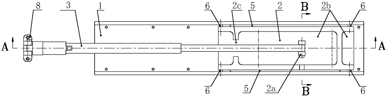
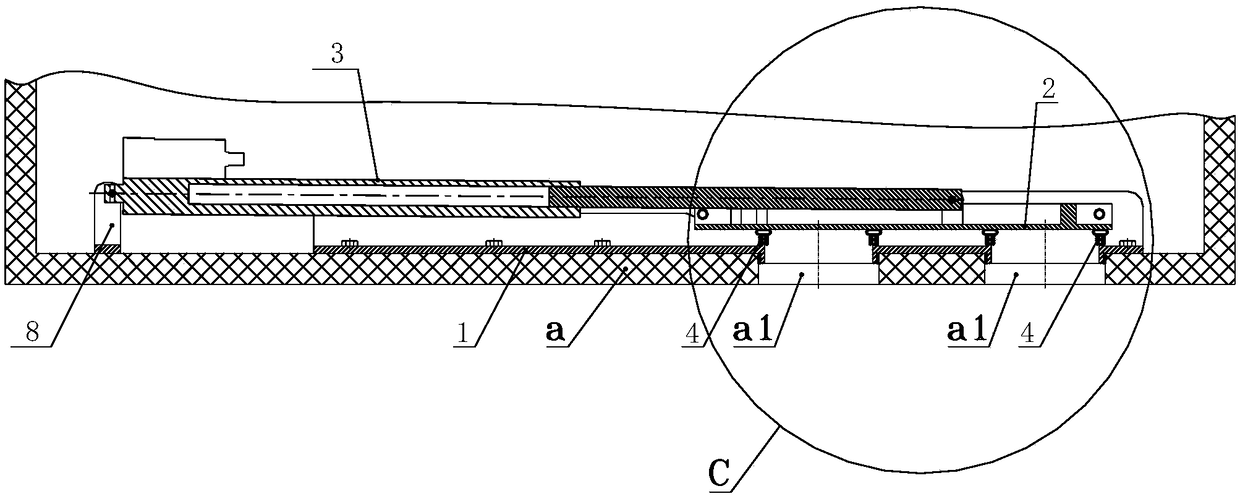
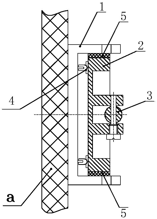
[0041] An automatic sealing mechanism for an orifice cover provided by the present invention includes: a fixed sliding seat 1, a sealing sliding plate 2 and an electric push rod 3, the fixed sliding seat 1 is a U-shaped frame structure, and the bottom of the U-shaped frame structure corresponds to A matching through hole 1a is provided at the position of the opening a1 on the bulkhead a, and the end of the through hole 1a facing the opening a1 is provided with a first protruding ring 1b that can be inserted into the opening a1. The end of the through hole 1a facing away from the orifice a1 is provided with a second protruding ring 1c, and a sealing ring 4 is set on the second protruding ring 1c, and on the two side walls of the U-shaped...


PUM


Abstract

An automatic sealing mechanism for a hole cover comprises a fixing sliding seat which is of a U-shaped frame structure, and a through hole is formed in the bottom of the U-shaped frame structure; the end, facing a hole, of the through hole is provided with a first protruded circular ring, and the end, back on to the hole, of the through hole is provided with a second protruded circular ring sleeved with a sealing ring; the two side walls of the U-shaped frame structure are each provided with two sliding grooves which are formed in a spaced mode, the sliding grooves comprise the long sliding grooves and the oblique sliding grooves, and the long sliding grooves are in parallel with the bottom of the U-shaped frame structure; one ends of the oblique sliding grooves are connected with the long sliding grooves in a transition mode, and the other ends of the oblique sliding grooves are obliquely formed by facing the bottom of the U-shaped frame structure; the two side walls of a sealing sliding plate are each provided with a sliding strip, and the positions, corresponding to the two sides of the sliding strips, of the side wall of the sealing sliding plate are each provided with a guiding sliding column; the guiding sliding columns are slidably installed in the sliding grooves in a limited mode, and a connecting block is arranged on the surface, back on to the sealing ring, of the sealing sliding plate; and the telescopic end of an electric push rod is movably installed on the connecting block, and the fixed end of the electric push rod is movably installed on the cabin wall. The automatic sealing mechanism is suitable for automatic sealing of the hole cover.

Description

technical field [0001] The invention relates to the mechanical field, in particular to an automatic sealing mechanism for an orifice cover. Background technique [0002] At present, some domestic special vehicles, feed production lines, hazardous chemical production lines and other equipment have holes reserved for functional purposes such as observation, retrieving, maintenance or testing, among which some holes are often opened and sealed . This kind of orifice needs to have a set of special protection mechanism or sealing cover. The manual sealing cover is used in the parts that are easy to reach by tools and manual operation, and the automatic sealing mechanism of the orifice cover is used in the occasions where manual operation is not convenient or the degree of automation is high. . According to the control mode, the automatic sealing mechanism of the orifice cover mainly includes electric type, pneumatic type and hydraulic type. At present, the main control method i...

Claims


Application Information

Patent Timeline
Patent Type & Authority Patents(China)
IPC IPC(8): E06B3/46E06B7/16E05F15/632
CPCE05F15/632E06B3/46E06B7/16
Inventor 李海峰李德胜陈圣荣王代宏黄碧洲王超
Owner HUBEI SANJIANG AEROSPACE WANFENG TECH DEV
Why Eureka
Try Eureka