A Resistance Welding Process for Liquid Storage Tank of Compressor

A technology of resistance welding and liquid storage tank, applied in resistance welding equipment, welding of curved seams, welding of roller electrodes, etc., can solve the problems of high energy consumption of welding process, high cost of welding seam, large working area, etc., and achieve economical savings. Welding materials, the effect of reducing welding costs and reducing site requirements

Active Publication Date: 2016-01-06
HERON INTELLIGENT EQUIP CO LTD
View PDF8 Cites 0 Cited by
  • Summary
  • Abstract
  • Description
  • Claims
  • Application Information

AI Technical Summary

Problems solved by technology

[0002] In the past, when it was necessary to weld the upper shell of the steel liquid storage tank and the butt joint steel pipe and copper pipe three components at the same time, brazing in the furnace was usually used for welding. This process requires a tunnel heating furnace, requires a large work site, and also needs to add solder , the welding cost is high, and the welding process has high energy consumption, low efficiency, and pollutes the environment
[0003] The Chinese invention patent with the application number of 200810029403 discloses a resistance welding method, which is a process for welding two workpieces, a copper pipe with a diameter of 7.8 mm and a steel shell, and a slightly larger copper pipe with a diameter of more than 9 mm cannot be used. The process method for welding

Method used


Image

  • A Resistance Welding Process for Liquid Storage Tank of Compressor
  • A Resistance Welding Process for Liquid Storage Tank of Compressor

Examples


Embodiment Construction

[0020] Embodiments of the present invention are described in detail below.

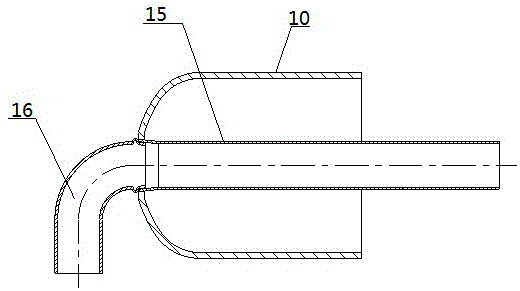
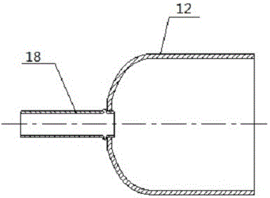
[0021] The embodiment of the present invention is to weld the upper shell of the air conditioner compressor liquid storage tank and its attached external butt joint copper pipe and internal butt joint steel pipe, abandoning the traditional high-cost and high-pollution brazing process in the furnace, and using resistance welding The process method replaces the traditional furnace brazing process, making the welding manufacturing process more environmentally friendly and cost-effective. refer to figure 1 As shown, the embodiment of the present invention mainly redesigns the welding structure of the upper casing of the liquid storage tank of the air conditioner, so that it has the feasibility of the resistance welding process, and discharges the copper pipe, the internal steel pipe, and the liquid storage tank from the upper casing of the liquid storage tank. The upper shell of the tank is firstly welde...


PUM

PropertyMeasurementUnit
diameteraaaaaaaaaa

Abstract

The invention discloses a resistance welding process of a fluid reservoir of a compressor. The resistance welding process of the fluid reservoir of the compressor is used for projection welding synchronous rings of an upper case body of the fluid reservoir, a steel tube and a copper tube and connecting a lower case body of the fluid reservoir in a seal welding. The resistance welding process comprises the following steps that: S1, welding end of the steel tube is cold pressed in the shape of a horn; S2, welding end of the copper tube is cold pressed in the shape of a convex ring and inserted into the horn-shaped welding end of the steel tube; S3, the copper tube contacts with the end face of the horn-shaped welding end of the steel tube before welding and a gap is formed between the copper tube and the inner side of the horn-shaped welding end of the steel tube, a line contact is formed between the steel tube and the fluid reservoir of the compressor to suspend the steel tube inside the upper case body of the fluid reservoir; S4, pressure is exerted on working parts by medium-frequency direct-current resistance ring projection welding to discharge and fusion weld the copper tube and the steel tube and the steel tube and the upper case body, and to seal weld the upper case body and the lower case body by resistance seam welding. The resistance welding process is capable of welding the fluid reservoir, downsizing working space, saving technological process and solder, reducing cost and meeting structural requirements of the fluid reservoir with the steel tube inside and the copper tube outside.

Description

technical field [0001] The invention relates to a welding process, in particular to a welding method between tube shell members of different materials. Background technique [0002] In the past, when it was necessary to weld the upper shell of the steel liquid storage tank and the butt joint steel pipe and copper pipe three components at the same time, brazing in the furnace was usually used for welding. This process requires a tunnel heating furnace, requires a large work site, and also needs to add solder , the welding cost is high, and the welding process has high energy consumption, low efficiency and pollutes the environment. [0003] The Chinese invention patent with the application number of 200810029403 discloses a resistance welding method, which is a process for welding two workpieces, a copper pipe with a diameter of 7.8 mm and a steel shell, and a slightly larger copper pipe with a diameter of more than 9 mm cannot be used. This process method is used for weldin...

Claims


Application Information

Patent Timeline
Patent Type & Authority Patents(China)
IPC IPC(8): B23K11/14B23K11/08B23K11/34
CPCB23K11/065B23K11/0935B23K11/14B23K11/20B23K11/34B23K2101/125B23K2103/18
Inventor 邹春芽
Owner HERON INTELLIGENT EQUIP CO LTD
Why Eureka
Try Eureka