High-gain active lossless clamping converter including built-in transformer and voltage-multiplying structure

A transformer and high-gain technology, applied in the field of high-gain active lossless clamp converters, can solve the problems of reducing conduction loss, complex coupled inductor structure, large switching loss, etc., to reduce voltage stress, simple circuit structure, and reduce The effect of conduction loss

Inactive Publication Date: 2014-04-23
杭州禾迈电力电子股份有限公司
View PDF6 Cites 6 Cited by
  • Summary
  • Abstract
  • Description
  • Claims
  • Application Information

AI Technical Summary

Problems solved by technology

[0003] The voltage gain of the conventional single-phase single-transistor boost DC-DC converter is only determined by the duty cycle, the voltage gain is limited, and it is difficult to meet the high-gain conversion requirements
The voltage stress of the power switch tube is relatively large, and it is difficult to use a low-voltage high-performance switch tube to reduce the conduction loss
Moreover, the switching tube of the converter works in a hard switching state, and the switching loss is relatively large
In order to realize the soft switching action of the Boost converter, in recent years, some soft switching schemes by adding active power switches or passive devices have been studied successively. Although these circuits realize the soft switching action, they cannot reduce the voltage stress of the switching tube. It is also impossible to realize the high-gain conversion of the system
In order to increase the voltage gain of the converter, one solution is to use switched capacitors, but this solution requires a large number of switch tubes, which increases the system cost; another solution is to use a complex three-winding coupled inductor solution. The disadvantage of the scheme is that the structure of the coupled inductor is complex, which is not conducive to industrial processing, and it is difficult to ensure the consistency of the circuit

Method used


Image

  • High-gain active lossless clamping converter including built-in transformer and voltage-multiplying structure

Examples


Embodiment Construction

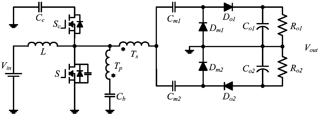
[0011] see figure 1 , in the high-gain active lossless clamp converter with built-in transformer and voltage doubler structure of the present invention,

[0012] The first end of the input inductor L is connected to the positive pole of the power supply Vin, the second end of the input inductor L is connected to the drain of the power switch S, the source of the clamp switch Sc, the second end of the built-in transformer primary winding Tp and The first end of the built-in transformer secondary winding Ts is connected, the first end of the built-in transformer primary winding Tp is connected to the first end of the DC blocking capacitor Cb, and the drain of the clamping switch Sc is connected to the first end of the clamping capacitor Cc Connected, the negative pole of the power supply Vin is connected to the source pole of the power switch tube S, the second end of the DC blocking capacitor Cb and the second end of the clamping capacitor Cc;

[0013] The second end of the se...


PUM


Abstract

The invention discloses a high-gain active lossless clamping converter including a built-in transformer and a voltage-multiplying structure. The high-gain active lossless clamping converter comprises one input inductor, one power switch tube, one clamping switch tube, two voltage-multiplying diodes, two output diodes, one clamping capacitor, one DC (Direct Current) blocking capacitor, two voltage-multiplying capacitors, two output capacitors and the built-in transformer, wherein the built-in transformer is provided with two windings. According to the high-gain active lossless clamping converter disclosed by the invention, the built-in transformer is utilized for expanding the voltage gain of the high-gain active lossless clamping converter and reducing the voltage stress of the power switch tube, the leakage inductance of the built-in transformer is utilized for realizing zero-voltage switching of the switch tubes and restraining inverse restoring current of the diodes, a clamping circuit formed by the clamping switch tube and the clamping capacitor is capable of effectively absorbing the voltage spike when the power switch tube is switched off and realizing the lossless transfer of energy, a voltage-multiplying circuit structure is utilized for further increasing the gain of the high-gain active lossless clamping converter and further reducing the voltage stress of the power switch tube and the diodes, the circuit structure is simple, the control is convenient, and the high-gain active lossless clamping converter is suitable for a photovoltaic grid-connected power generation conversion occasion in small power, high gain and high efficiency.

Description

technical field [0001] The invention relates to a DC-DC converter and its application, in particular to a high-gain active non-destructive clamp converter with a built-in transformer and a voltage doubler structure. Background technique [0002] In the photovoltaic power generation system, since the output voltage of a single photovoltaic cell is low, and the DC bus voltage required for inverter grid-connected power generation is relatively high, a first-stage DC-DC converter is required to convert the low-voltage DC into a power grid suitable for grid-connected power generation. high voltage direct current. In the distributed photovoltaic power generation scheme, the power capacity of a single photovoltaic cell is small, but the requirements for efficiency are high. Therefore, how to realize a single-stage converter with high gain, high efficiency and simple structure is of great significance for promoting the development of the photovoltaic industry. [0003] The voltage...

Claims


Application Information

Patent Timeline
IPC IPC(8): H02M3/335H02M5/08
CPCY02E10/56
Inventor 李威辰赵一杨波
Owner 杭州禾迈电力电子股份有限公司
Why Eureka
Try Eureka