Laser additive manufacturing method and equipment for metal parts

A metal parts, laser additive technology, applied in the direction of metal material coating process, coating, etc., can solve the problems of heavy load, overweight machine tool, increased manufacturing cost and difficulty coefficient, etc., to reduce the complexity of the device, spare metal powder The effect of reduced weight and high forming accuracy

Active Publication Date: 2016-05-25
TECH LASER TECH SHANGHAI CO LTD
View PDF3 Cites 0 Cited by
  • Summary
  • Abstract
  • Description
  • Claims
  • Application Information

AI Technical Summary

Problems solved by technology

If it is really necessary to use SLM technology to manufacture large-size parts, a large-size forming cylinder must be used. The large amount of powder carried by the large-size forming cylinder will bring a heavy load to the machine tool, making the mechanical components such as pistons and screw rods in the SLM forming equipment loaded. The load of the equipment is large, and the manufacturing cost and difficulty factor of the equipment are greatly increased.
[0012] To sum up, LMD technology is generally used to manufacture large-scale metal parts with relatively simple shapes and low dimensional accuracy requirements; while SLM technology is used to manufacture metal parts with complex shapes and high dimensional accuracy requirements, but it is currently impossible to manufacture large-scale metal parts. Dimensional Metal Parts
Using the SLM method of large-sized forming cylinders to manufacture large metal parts will bring many technical difficulties to the manufacture of SLM equipment. For example, the entire forming cylinder must be filled with excess alloy powder to complete the part manufacturing, which will make the machine tool overweight. , the complexity of mechanical equipment is greatly increased and the cost of equipment manufacturing is greatly increased

Method used


Image

  • Laser additive manufacturing method and equipment for metal parts
  • Laser additive manufacturing method and equipment for metal parts
  • Laser additive manufacturing method and equipment for metal parts

Examples


example 1

[0085] Examples 1 to 4 use Figure 4 The structure shown is realized.

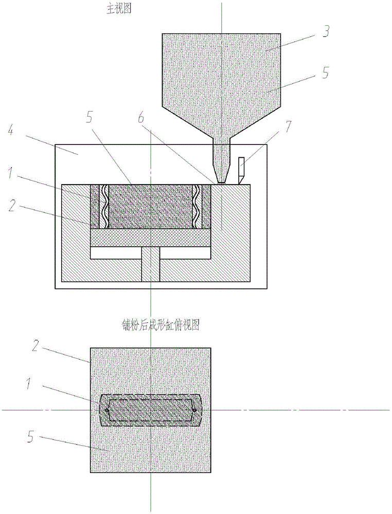
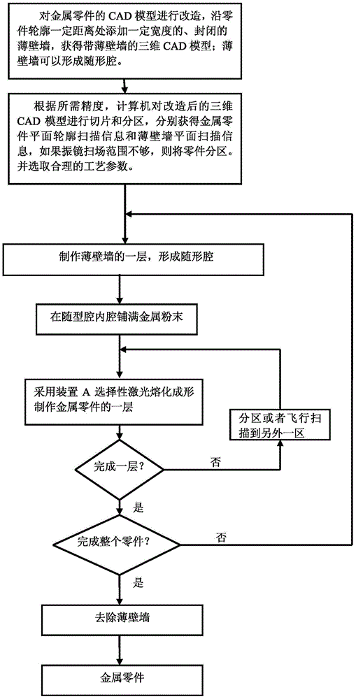
[0086] (1) Transform the CAD model of the metal part 1 to obtain the layered contour information of the metal part 1 and the thin wall 8: add a 4mm wide thin wall 8 and thin wall 8 at a place 1mm away from the periphery of the metal part contour Close to form a "conformal cylinder" 9; according to the required accuracy, use a computer to slice the transformed 3D CAD model in layers, and obtain the scanned contour information of each layer of the thin wall 8 and the metal part 1 respectively;

[0087] (2) Using LMD technology to manufacture a layer of thin wall 8: the laser is converted to the light guide system 23 through the beam converter 27, reaches the optical focusing system 22, and then focuses on the working surface to form a suitable spot, and the control system controls the machine tool to drive the laser and the optical focusing system to scan along the outline and path planning of the thin-wall...

example 2-4

[0095] The process is as in Example 1, and the process parameters are shown in Table 1 below.

example 5

[0097] This example adopts the method for welding to prepare thin-walled wall 8, and its steps are as follows:

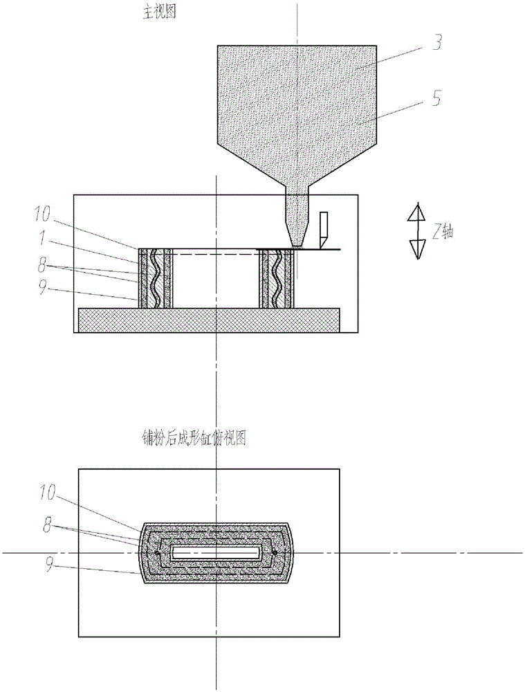
[0098] (1) Transform the 3D CAD model of the metal part to obtain the layered contour information of the metal part 1 and the thin wall 8 . Transform the three-dimensional CAD model of the metal part 1 in the computer control system software: add a closed outer edge (i.e. thin-walled wall 8) with a width of 1 mm at a place 25 mm away from the edge contour of the metal part 1, and the thin-walled wall 8 can be Form follow-up cylinder 9. According to the shape of the part, the conformal cylinder 9 can be a cavity that surrounds the entire part, or it can be divided into multiple cavities that can form a closed area according to the characteristics of the part; according to the required dimensional accuracy of the manufactured part, Using a computer to carry out layered slices on the modified CAD model with thin-walled walls to obtain the laser plane scanning profile ...


PUM

PropertyMeasurementUnit
thicknessaaaaaaaaaa
thicknessaaaaaaaaaa
thicknessaaaaaaaaaa

Abstract

The invention discloses a laser additive manufacturing method and a laser additive manufacturing device of metal parts. In the laser additive manufacturing method, a layered-manufactured profile-followed cylinder is used as a forming cylinder, namely before each metal part layer is manufactured, a layer of closed thin wall is manufactured, the formed cavity is used as the profile-followed cavity, the height of the profile-followed cavity is the same as that of the metal part layer to be manufactured, and the shape of the profile-followed cavity is adapted to that of the metal part layer to be manufactured, so as to provide a plane reference and a cavity for laying powder; the layered-manufactured profile-followed cylinder is used, a scanning galvanometer is used for performing selective laser melting and forming, the metal part layers are manufactured layer by layer, layers of the profile-followed cavities are finally stacked to form the profile-followed cylinder, and the layers of metal parts are stacked to form metal parts. The laser additive manufacturing device comprises a laser galvanometer melting and forming device and a thin wall preparation device which alternatively work, so as to accomplish the selective laser melting and forming process. The method and the device keep the advantages of the selective laser melting (SLM) metal additive manufacturing technology, uses the profile-followed cylinder to break the limit of the conventional SLM device fixed-size forming cylinder, and thus achieving the high-precision manufacture of the large-size even over-sized parts.

Description

technical field [0001] The invention belongs to the technical field of laser additive manufacturing, and in particular relates to an additive manufacturing method and equipment for high-precision metal parts, and is especially suitable for the manufacture of large-sized or even super-large-sized complex metal parts. Background technique [0002] In recent years, laser additive manufacturing technologies based on "discrete-stacking" and "additive forming" have been able to directly manufacture metal parts with a density of nearly 100% from CAD models and metal powders. Commonly used metal materials such as tool steel, stainless steel, nickel alloy, copper alloy, titanium alloy and tungsten alloy have been successfully trial-produced, and the manufactured metal parts are gradually moving towards practical industrial applications. [0003] At present, there are two ways to directly manufacture 100% density metal parts by laser additive manufacturing technology: one is based on ...

Claims


Application Information

Patent Timeline
Patent Type & Authority Patents(China)
IPC IPC(8): C23C24/10
Inventor 曾晓雁朱海红王福德王泽敏陈立新李重洋张红波
Owner TECH LASER TECH SHANGHAI CO LTD
Why Eureka
Try Eureka