
Energy-saving vacuum double cavity holding furnace

A holding furnace and energy-saving technology, applied in the field of aluminum alloy casting, can solve the problems of shortening the life of heating wires, deteriorating the environment of the work area, and high cost of use, so as to improve the effect and efficiency of degassing, improve the effect of heat insulation, and prolong the service life Effect

Inactive Publication Date: 2014-04-09
WUXI XIYANGKANG SCI & TECH
View PDF5 Cites 2 Cited by
  • Summary
  • Abstract
  • Description
  • Claims
  • Application Information

AI Technical Summary

Problems solved by technology

[0002] In the process of casting aluminum alloy products, in order to ensure continuous production, each production line is equipped with two well-type heat preservation furnaces to heat and heat the molten aluminum and use them in turn. The effect is not ideal. Not only does it increase and deteriorate the environment of the work area, but also needs to use air conditioners to cool down in summer, which consumes a lot of energy; the current electric heating wire and the crucible rely on air conduction, which not only has a large temperature difference between the two, but also shortens the life of the electric heating wire. , the control accuracy is also poor; the graphite ceramic crucible used is not only costly, but also easy to crack and has a short life; the refining degassing must use the rotor degasser, which increases the consumables and cost; the use of immersion electric heaters or surface heating devices The high-quality holding furnace not only has less functions but high investment, but also high cost of use

Method used


Image

  • Energy-saving vacuum double cavity holding furnace
  • Energy-saving vacuum double cavity holding furnace

Examples


Embodiment Construction

[0017] The specific implementation manners in the present invention will be further described below in conjunction with the accompanying drawings.

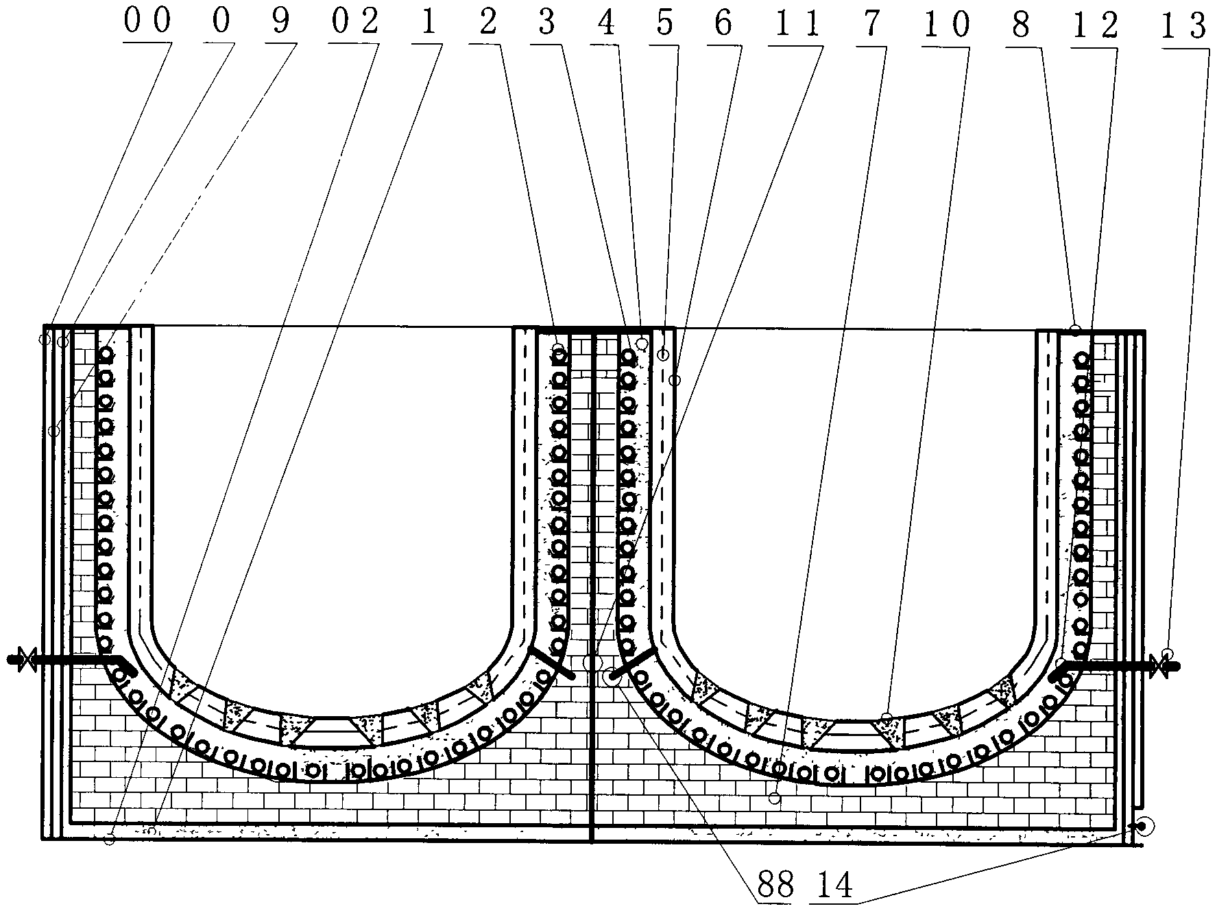
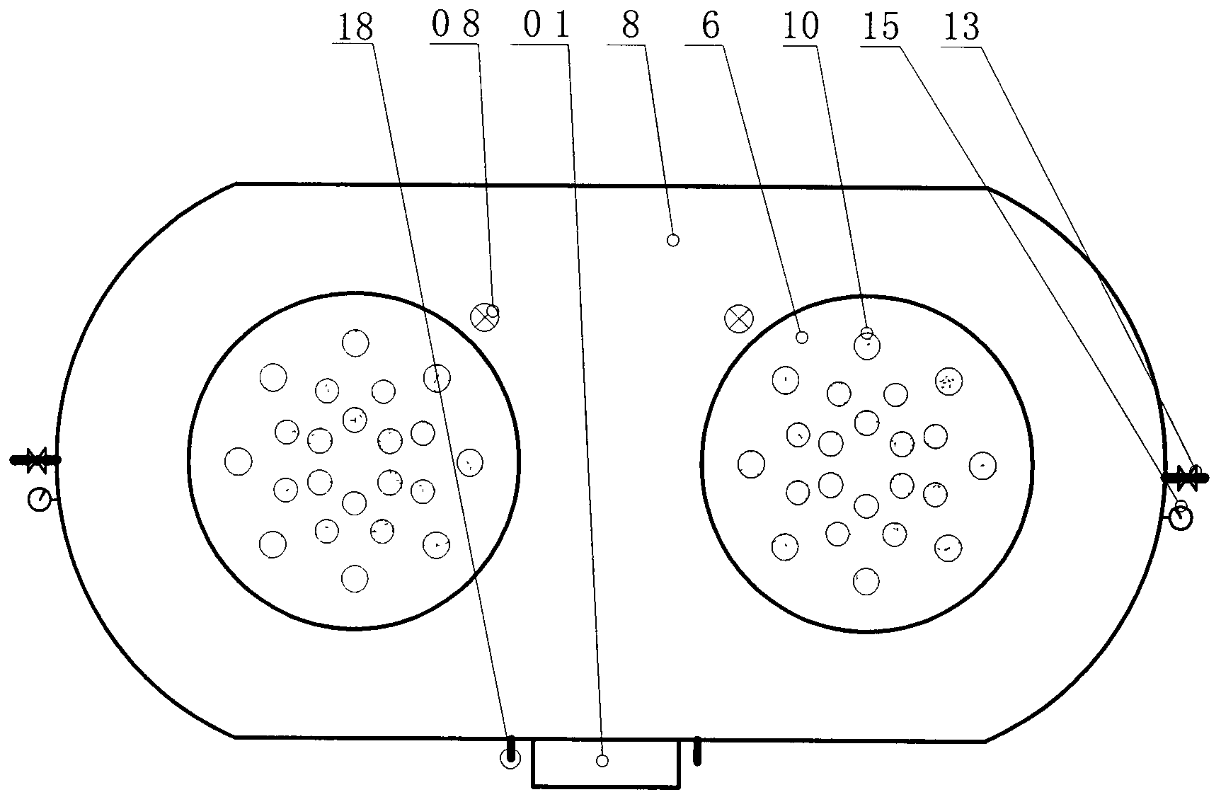
[0018] figure 1 , figure 2 Including furnace shell 00, inner shell 0, distribution box 01, furnace bottom 02, insulation material 1, heating wire 2, wire brick 3, magnesia 4, carbon fiber reinforcement rib 5, crucible 6, furnace brick 7, injection Sand port 08, furnace cover 8, thermocouple 88, reinforcing rib 9, vacuum nozzle 10, sealing plate 11, air intake pipe 12, degassing control valve 13, vacuum nozzle 14, vacuum gauge 15, thermocouple terminal 18, etc.

[0019] like figure 1 , figure 2 As shown, the present invention is an energy-saving vacuum double-chamber holding furnace, including a vacuum furnace shell mechanism, a heating mechanism, and a degassing crucible mechanism.

[0020] The vacuum furnace shell mechanism includes a furnace shell 00, an inner shell 0, a reinforcing rib 9, a furnace cover 8, a sand injecti...


PUM


Abstract

An energy-saving vacuum double cavity holding furnace comprises a vacuum furnace shell mechanism, a heating mechanism and a degassing crucible mechanism, wherein the vacuum furnace shell mechanism is provided with a furnace shell, an inner shell, reinforcing ribs, a furnace cover, a sand injecting opening and a furnace bottom, wherein a vacuum cavity is formed between the inner shell and the furnace shell, the heating mechanism is provided with an electric heating wire, a power distribution box, magnesia and a thermocoupler, and the degassing crucible mechanism is provided with a crucible, a degassing brick, a gas inlet tube and a degassing control valve. The temperature of the heating mechanism and the temperature of the degassing crucible mechanism are preserved through a vacuum furnace sleeve, the thermal insulating effect is improved, heat of the crucible is directly conducted through the magnesia filled into the periphery of the electric heating wire, the working temperature on the surface of the electric heating wire is lowered, the temperature difference between the electric heating wire and the crucible is balanced, and the service life of the electric heating wire is prolonged. The carbon fiber reinforcing ribs arranged in the crucible are adopted to effectively prevent fracture of the crucible; the degassing brick arranged on the bottom of the crucible is adopted to replace the rotor degassing procedure, the degassing effect and the degassing efficiency are improved, and energy and cost are saved.

Description

technical field [0001] The invention relates to the field of aluminum alloy casting, in particular to an energy-saving vacuum double-chamber holding furnace. Background technique [0002] In the process of casting aluminum alloy products, in order to ensure continuous production, each production line is equipped with two well-type heat preservation furnaces to heat and heat the molten aluminum and use them in turn. The effect is not ideal. Not only does it increase and deteriorate the environment of the work area, but also needs to use air conditioners to cool down in summer, which consumes a lot of energy; the current electric heating wire and the crucible rely on air conduction, which not only has a large temperature difference between the two, but also shortens the life of the electric heating wire. , the control accuracy is also poor; the graphite ceramic crucible used is not only costly, but also easy to crack and has a short life; the refining degassing must use the ro...

Claims


Application Information

Patent Timeline
Patent Type & Authority Applications(China)
IPC IPC(8): F27B14/06F27B14/10F27B14/14
Inventor 邵宏
Owner WUXI XIYANGKANG SCI & TECH
Learn More