Sand-blasting protective clamp for centrifugal impeller combination

A technology for protecting fixtures and centrifugal impellers, applied in manufacturing tools, processing devices for used abrasives, abrasives, etc., to achieve the effects of improving production efficiency and product quality, saving production costs, and shortening the processing cycle

Active Publication Date: 2014-04-09
CHINA HANGFA CHANGZHOU LANXIANG MACHINERY CO LTD
View PDF5 Cites 3 Cited by
  • Summary
  • Abstract
  • Description
  • Claims
  • Application Information

AI Technical Summary

Problems solved by technology

It takes about 3.5 hours to trim and paste the tape. After the sand blowing, it needs to clean the sand on the parts and clean the mucus of the medical tape with ethyl acetate. It takes about 3 hours again, and this process requires workers with high technical level operate

Method used


Image

  • Sand-blasting protective clamp for centrifugal impeller combination
  • Sand-blasting protective clamp for centrifugal impeller combination
  • Sand-blasting protective clamp for centrifugal impeller combination

Examples


Embodiment

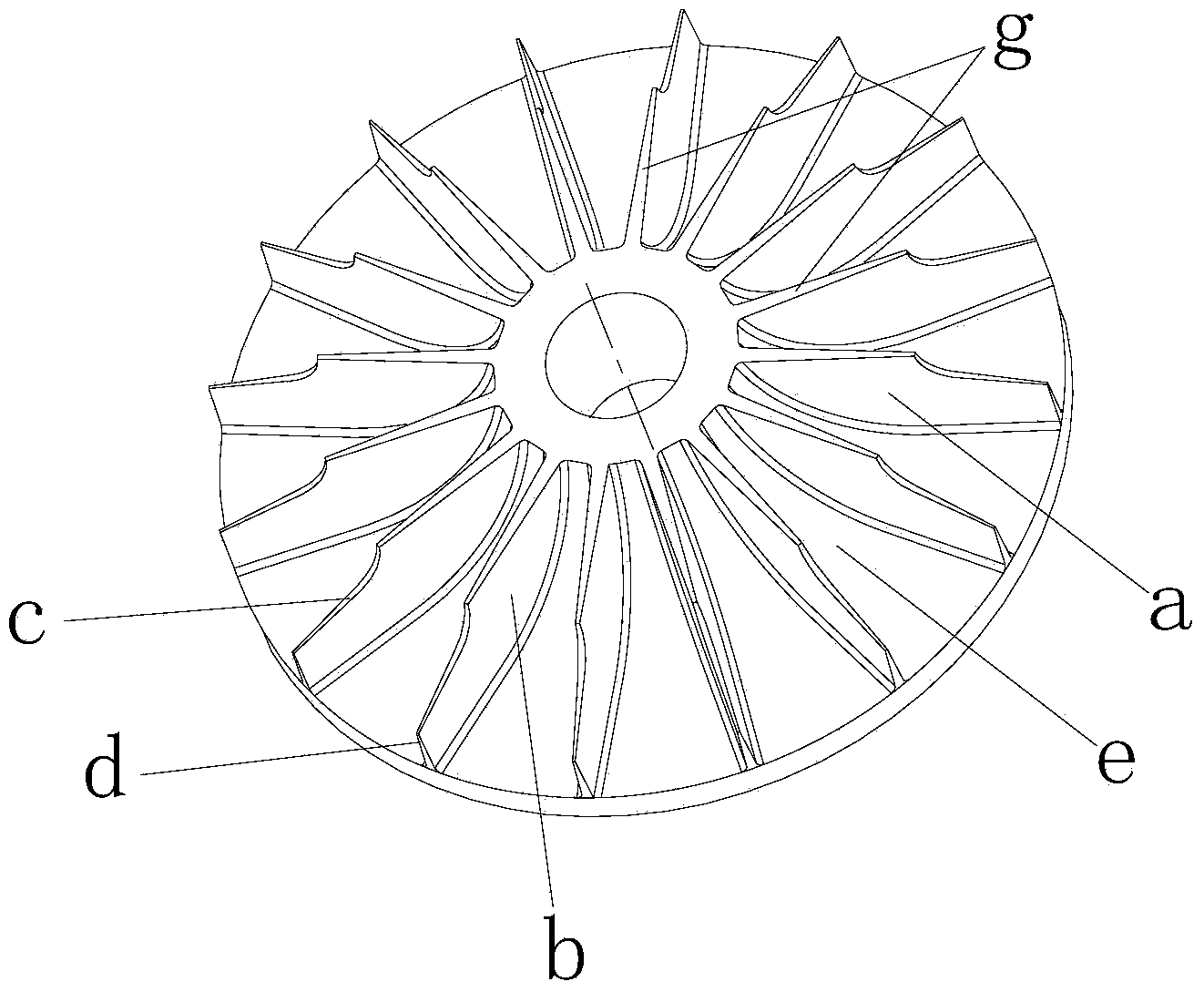
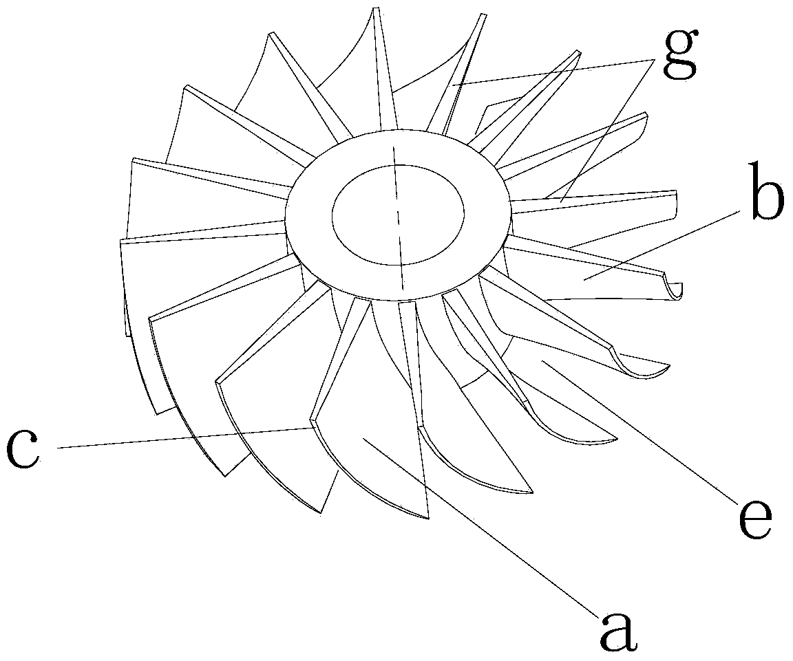
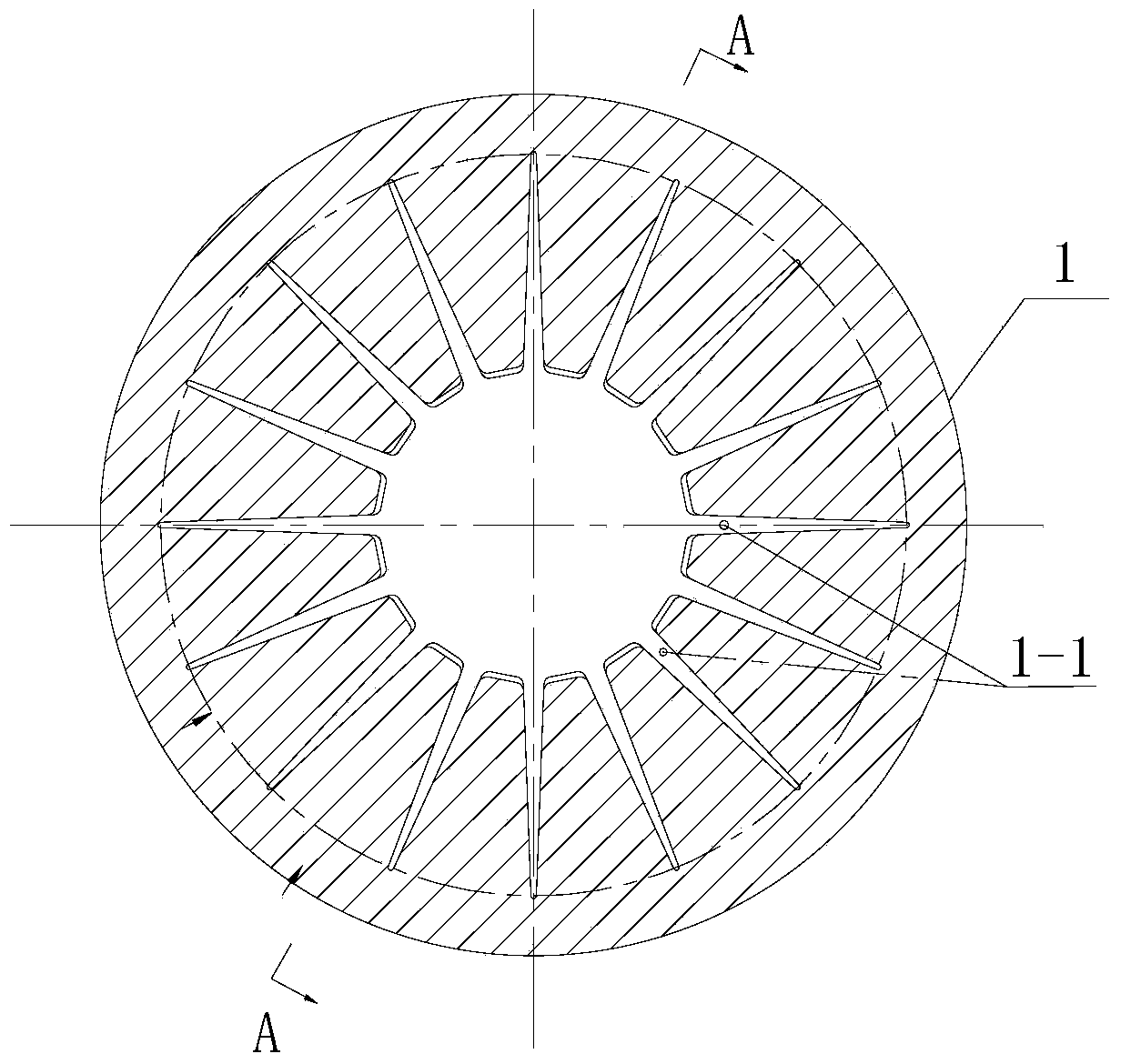
[0020] See figure 1 As shown in -4, a centrifugal impeller combined sand blowing protection fixture includes: first and second protection fixtures.

[0021] The first protective fixture includes: a first annular cover plate 1, a plurality of isosceles triangle notches 1-1 are distributed on the inner circle of the first annular cover plate 1, each notch 1-1 on the first annular cover plate 1 1 corresponds to the distribution of the surface to be sanded on each blade of the impeller, and the surface to be sanded on each blade of the impeller is suitable for being respectively embedded in each notch on the first annular cover plate 1- 1, and the assembly gap between each notch 1-1 on the first annular cover plate 1 and the surface to be sand-blown in the notch 1-1 is 0.3 to 0.6mm (preferably 0.5mm).

[0022] The second protective fixture includes: a second annular cover plate 1', a plurality of isosceles triangle notches 1-1 are distributed on the inner circle of the second ann...


PUM


Abstract

The invention relates to a sand-blasting protective clamp for centrifugal impeller combination. The sand-blasting protective clamp comprises a first protective clamp and a second protective clamp, wherein the first protective clamp comprises a first annular cover plate; a plurality of isosceles triangle notches are formed in the inner ring of the first annular cover plate; the distribution of each notch on the first annular cover plate and a surface to be sand-blasted on each vane of the impeller is in a one-to-one correspondence manner; the surface to be sand-blasted on each vane of the impeller is suitable for being embedded in each notch on the first annular cover plate; the assembling gap between each notch on the first annular cover plate and the surface to be sand-blasted arranged in the notch is 0.3-0.6 mm; the size of the gap facilitates the assembling and also can prevent sand from passing through a non-sand-blasting surface scratched by the gap. With the clamp, the labor intensity of workers is greatly alleviated, the production efficiency and product quality are improved, the production cost is reduced, and the processing cycle of parts is shortened.

Description

technical field [0001] The invention relates to a centrifugal impeller combined sand blowing protective fixture. Background technique [0002] Such as figure 1 and 2 , the centrifugal impeller combination is a part of the compressor part of the aero-engine. This part is glued together by the impeller and the wind deflector with adhesive strips, and is positioned with the help of three positioning pins. The impeller and the wind deflector are both made of stainless steel. Each one has 16 leaves. When the compressor is working, the shock absorption performance of the split structure combined with the centrifugal impeller is better than that of the integral type. [0003] Before the assembly of this component, it is necessary to blow sand on the bonding surface f of the impeller and the wind deflector to increase the roughness of the bonding surface, thereby enhancing the strength of the bonding of the two parts. Before gluing, processes such as rubber mixing, rubber stripp...

Claims


Application Information

Patent Timeline
IPC IPC(8): B24C5/00B24C9/00
Inventor 蔡立猛张军彭晨
Owner CHINA HANGFA CHANGZHOU LANXIANG MACHINERY CO LTD
Why Eureka
Try Eureka