
A kind of micro-bending device and method of clustered and combined mold sleeves

A micro-bending and combined technology, applied in metal processing equipment, forming tools, manufacturing tools, etc., can solve the problems of low precision of forming workpieces, high energy consumption of laser heating, and difficulties in mold manufacturing, so as to improve positioning efficiency and accuracy , Conducive to mass production, convenient selection of bolts

Active Publication Date: 2015-08-26
HUAWEI TEHCHNOLOGIES CO LTD
View PDF7 Cites 0 Cited by
  • Summary
  • Abstract
  • Description
  • Claims
  • Application Information

AI Technical Summary

Problems solved by technology

In the field of microplastic forming, Edward G. Wenskis of the United States designed a forming device for micro-stretching, the patent number is US6983658, which is only used for micro-tensile testing and is difficult to apply to micro-bending
Chinese patent 03132554.8 reports a precision micro-plastic forming system developed by Harbin Institute of Technology. Its principle is to use piezoelectric ceramics as a driver to press and form, but it does not refine micro-bending forming.
Chinese patent 200510022725.1 reports a superplastic extrusion molding device for micro-miniature parts from Northwestern Polytechnical University, but the device is only designed for superplastic materials, and the applicable area is narrow
[0005] Summarizing the above studies and reports, the existing micro-bending forming technology has the following shortcomings: 1. In terms of laser, the temperature gradient effect of the material is used, and the surface temperature of the material is not uniform, the deformation of the material is not uniform, and the bending is generated through laser heating, but this method has defects.
Because the degree of laser heating is difficult to control, the precision of the final formed workpiece is not high, so this technology is still in the experimental stage; secondly, the energy consumption of laser heating is very high, which does not conform to the modern production concept of sustainable development, and the production cost is also high
2. The electrochemical method has relatively high processing costs, a high degree of specialization, and a long production cycle, which is not conducive to wide application
Moreover, the surface quality of the bent material produced by the electrochemical method is not high, and the strength is relatively low.
3. The premise of the superplastic microforming method is to use superplastic materials, the raw materials are limited, and there are fewer materials that can meet the requirements of micro devices, the production cost is high, and mass production is not possible
In addition, superplastic materials need specific conditions to exhibit superplasticity, the conditions are harsher, and the production cost is higher
4. It is very difficult to produce micro-curved parts by using the traditional mold method, and because the micro-devices are very small, the stiffness of the punch is relatively poor, and the performance is relatively poor.

Method used


Image

  • A kind of micro-bending device and method of clustered and combined mold sleeves
  • A kind of micro-bending device and method of clustered and combined mold sleeves
  • A kind of micro-bending device and method of clustered and combined mold sleeves

Examples


Embodiment Construction

[0029] The devices and methods described will be described in detail below in conjunction with the accompanying drawings.

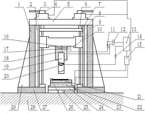
[0030] The forming device proposed by the present invention includes six parts: a mounting table 28, a translational loading workbench, a data acquisition system, a bundled and combined punch mold assembly 19, a die assembly and a control system. The power source is provided by the translational loading workbench, and the data acquisition system provides the information required for control. The mold set cluster combined punch assembly 19 and the die assembly complete the forming and bending. The control system mainly controls the displacement, speed and to medium. The details of each part will be introduced in detail in conjunction with the figure below.

[0031] combine figure 1 , the translational loading table consists of a fixed base 27, an angle iron fixed block 29, a loading frame 1, a square guide rail 2, a screw 8, a sliding panel 9, a fixing p...


PUM


Abstract

The invention relates to a die sleeve cluster combined type micro-bending device and method. The die sleeve cluster combined type micro-bending device comprises two fixed bases and two loading frames, the top ends of the two loading frames are connected into a whole through an installation board, and two stepping motors I are arranged on the upper surface of the installation board; a square guide rail and a screw rod are arranged on each loading frame; the two screw rods are connected with the two stepping motors I through couplings; each screw rod is connected with a sliding panel, and an H-shaped board is connected between the sliding panels; the lower end of the H-shaped board is connected with a U-shaped board which is provided with a male die assembly; a mounting table is provided with a two-dimensional moving table, a female die fixing board is arranged on the upper surface of the two-dimensional moving table, a female die is arranged on the female die fixing board, and a positioning block is arranged on the female die. When the die sleeve cluster combined type micro-bending device is used, according to the thickness of a micro-bent part and the width of the female die, a metal wire with the matched diameter and a corresponding die sleeve are replaced. The die sleeve cluster combined type micro-bending device and method solve the problems that micro-bent male dies are difficult to manufacture, and the male dies are changed frequently because the thicknesses of micro-bent parts change.

Description

technical field [0001] The technical field that the present invention relates to is the field of micro-plastic forming, and refers to a forming device and method that uses a tensioned mold cover bundled and combined metal wire harness instead of a punch to complete micro-bending. Background technique [0002] With the rapid development of the economy, the continuous advancement of science and technology, the scope of modern industry is also expanding, and the trend of product miniaturization is also increasingly apparent, especially the breakthrough development of micro-electro-mechanical systems and integrated technology. Microplastic forming demand is also increasing. At the same time, in the fields of electronics, medicine, and precision instruments, micro-devices are also playing an increasingly important role. However, because the product is very small, the degree of difficulty in the processing technology is also greatly increased. Factors such as feed rate, loading ...

Claims


Application Information

Patent Timeline
Patent Type & Authority Patents(China)
IPC IPC(8): B21D5/00B21D7/00B21D11/00B21D37/10
Inventor 王匀许桢英薛小峰朱金鑫朱凯杜金星徐吉伟魏人杰于浩
Owner HUAWEI TEHCHNOLOGIES CO LTD
Learn More