A high-efficiency selective emitter solar cell laser doping method

A solar cell and laser doping technology, applied in photovoltaic power generation, circuits, electrical components, etc., can solve the problems of low peripheral energy density, reduced absorption, uneven distribution of beam energy density, etc., to reduce uneven deformation of the battery, reduce The probability of local breakdown and the effect of reducing beam energy loss

Inactive Publication Date: 2016-02-24
WENZHOU ADVANCED MFG TECH INST OF HUAZHONG UNIV OF SCI & TECH
View PDF6 Cites 0 Cited by
  • Summary
  • Abstract
  • Description
  • Claims
  • Application Information

AI Technical Summary

Problems solved by technology

However, due to the large radius of the laser beam waist spot, the uneven distribution of beam energy density, high energy density in the center and small energy density in the periphery, the direct laser doping method has certain disadvantages.
For example, the surface distribution of the heavily doped region is wider, which reduces the absorption of short-wavelength photons in the emitter region, that is, reduces the blue light response of the battery; the doping depth of the central region is large, which easily leads to local conduction between the N+ region and the P+ region of the battery. That is, it causes partial breakdown of the PN terminal, which leads to battery failure.
In addition, the traditional laser doping process uses a Gaussian beam to scan the front electrode area one by one, which takes 2-3 seconds for each cell, and the efficiency is low

Method used


Image

  • A high-efficiency selective emitter solar cell laser doping method
  • A high-efficiency selective emitter solar cell laser doping method
  • A high-efficiency selective emitter solar cell laser doping method

Examples


Embodiment 1

[0029] A laser doping method for a highly efficient selective emitter solar cell, comprising the following steps:

[0030] (1) Use a P-type polycrystalline silicon wafer with a size of 156mm×156mm, clean and texture it, clean and texture the crystalline silicon wafer, use the thermal diffusion process to perform preliminary impurity diffusion on the silicon wafer, and control the concentration of impurity sources and diffusion time Make the crystalline silicon square resistance value reach the required size (such as 70-90Ω), so that a pre-coating layer is formed on the surface of the crystalline silicon wafer;

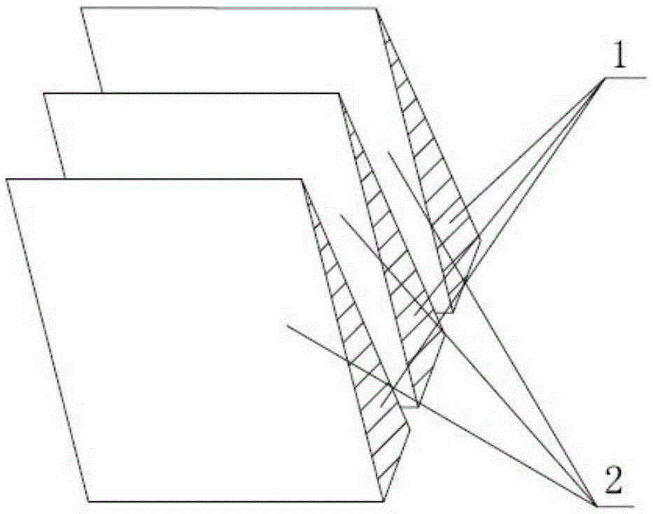
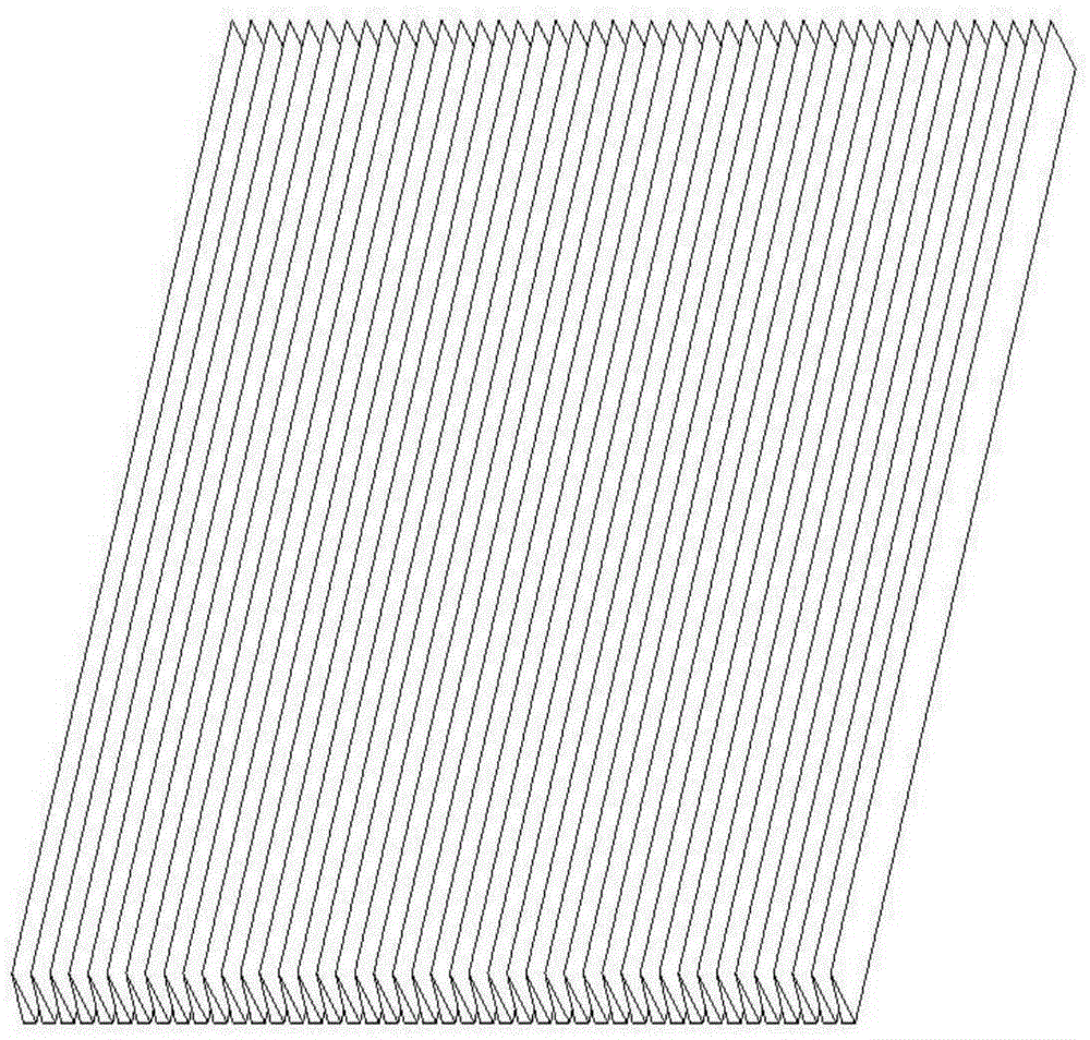
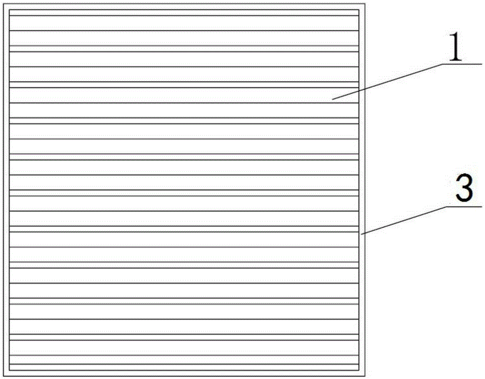
[0031] (2) Send the P-type polysilicon wafer directly under the mask plate, so that the geometric center of the P-type polysilicon wafer coincides with the geometric center of the mask plate, and the light leakage gap of the mask plate coincides with the fine grid of the cell on the P-type polysilicon wafer , the mask plate is closely attached to the P-type polysilicon...

Embodiment 2

[0037] A laser doping method for a highly efficient selective emitter solar cell, comprising the following steps:

[0038] (1) Use a P-type polycrystalline silicon wafer with a size of 156mm×156mm, clean and texture it, clean and texture the crystalline silicon wafer, use the thermal diffusion process to perform preliminary impurity diffusion on the silicon wafer, and control the concentration of impurity sources and diffusion time Make the square resistance of crystalline silicon at 70-90Ω, so that a pre-coating layer is formed on the surface of crystalline silicon wafer;

[0039] (2) Send the P-type polysilicon wafer directly under the mask plate, so that the geometric center of the P-type polysilicon wafer coincides with the geometric center of the mask plate, and the light leakage gap of the mask plate coincides with the fine grid of the cell on the P-type polysilicon wafer , the mask plate is closely attached to the P-type polysilicon wafer;

[0040] The mask plate inclu...


PUM


Abstract

The invention provides an efficient selective emitter solar battery laser doping method. The method comprises the following steps: (1) cleaning and texturing a crystal silicon wafer, and performing primary impurity diffusion on the silicon wafer by adopting a thermal diffusion process to form a pre-coated layer on the surface of the crystal silicon wafer; (2) conveying the crystal silicon wafer to the lower side of a mask plate till the geometric center of the crystal silicon wafer is overlapped with the geometric center of the mask plate, the light leaking gap of the mask plate is overlapped with a fine grid of a battery piece on the crystal silicon wafer, and the mask plate clings close to the crystal silicon wafer; (3) performing laser scanning doping by using strip-shaped uniform laser beams. Compared with the prior art, the efficient selective emitter solar battery laser doping method has the advantages that the laser energy can be utilized more fully, the blue light response reduction can be avoided, the PN-junction local breakdown can be avoided, the uniformity of the doping depth is increased while the laser doping efficiency is increased, and non-uniform battery deformation caused by local doping is reduced.

Description

technical field [0001] The invention relates to laser doping selective emitter technology, in particular to a high-efficiency selective emitter solar cell laser doping method. Background technique [0002] Selective emitter technology is an important means for manufacturers of crystalline silicon solar cells to improve cell efficiency and reduce cost per watt. Due to the characteristics of low cost, low investment and compatibility with traditional solar cell production lines, the laser doping process has attracted much attention. The direct laser doping method has a simple and controllable process, can achieve regional heavy doping, has a high activation rate, and has a very obvious effect on improving the photoelectric conversion efficiency. However, due to the large radius of the laser beam waist spot, the uneven distribution of beam energy density, high energy density in the center and low energy density in the periphery, the direct laser doping method has certain disad...

Claims


Application Information

Patent Timeline
Patent Type & Authority Patents(China)
IPC IPC(8): H01L31/18
CPCH01L21/268H01L31/1804Y02E10/547Y02P70/50
Inventor 秦应雄王雪余建堤谈贤杰周日发
Owner WENZHOU ADVANCED MFG TECH INST OF HUAZHONG UNIV OF SCI & TECH
Why Eureka
Try Eureka