Self-lubricating crankshaft and rotary compressor, air conditioner and heat-pump water heater using same

A self-lubricating, crankshaft technology, applied in the crankshaft field, can solve the problems of not adapting to the operation of the compressor in the later period of its life, poor crankshaft operation adaptability, compressor failure and damage, etc., to achieve enhanced operation adaptability, reduced friction coefficient, reduced The effect of partial grinding

Active Publication Date: 2014-04-02
ZHUHAI LANDA COMPRESSOR +1
View PDF10 Cites 8 Cited by
  • Summary
  • Abstract
  • Description
  • Claims
  • Application Information

AI Technical Summary

Problems solved by technology

[0002] Existing rotary compressors mainly rely on the oil guide plate installed on the inner side of the lower part of the crankshaft to supply oil. For compressors dedicated to heat pump water heaters, compressors that operate for a long time under harsh working conditions such as T3, and inverter compressors that operate at low frequencies, often Insufficient oil supply to the crankshaft, thin lubricating oil film will easily cause reliability problems such as serious wear and even jamming of the main and auxiliary friction pairs of the compressor crankshaft and eccentric circle parts; at the same time, after the compressor has been running for a period of time, the Parts are worn to a certain extent and even impurities are generated. The existing compressor crankshaft cannot automatically flush the generated impurities, which is particularly prone to reliability problems such as compressor jamming. Adapt to late compressor life operation
like figure 1 and figure 2 As shown, especially the thrust surface of the crankshaft of the rotary compressor bears the weight of the motor rotor assembly of the compressor and the crankshaft itself, and forms a pair of high-speed moving plane sliding friction pairs with the plane of the lower flange during high-speed operation , although there is a certain amount of refrigeration oil lubrication between them, the two planes are tightly attached under the action of gravity, and the lubrication is not ideal. In the actual production process, thrust surface wear or lower flange wear often occurs, and long-term wear Ultimately lead to compressor failure and damage

Method used


Image

  • Self-lubricating crankshaft and rotary compressor, air conditioner and heat-pump water heater using same
  • Self-lubricating crankshaft and rotary compressor, air conditioner and heat-pump water heater using same
  • Self-lubricating crankshaft and rotary compressor, air conditioner and heat-pump water heater using same

Examples


Embodiment 1

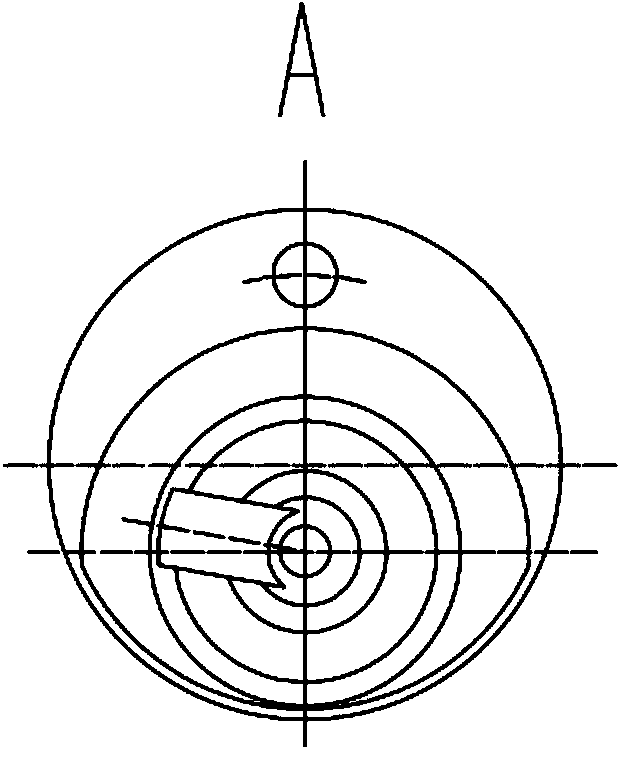
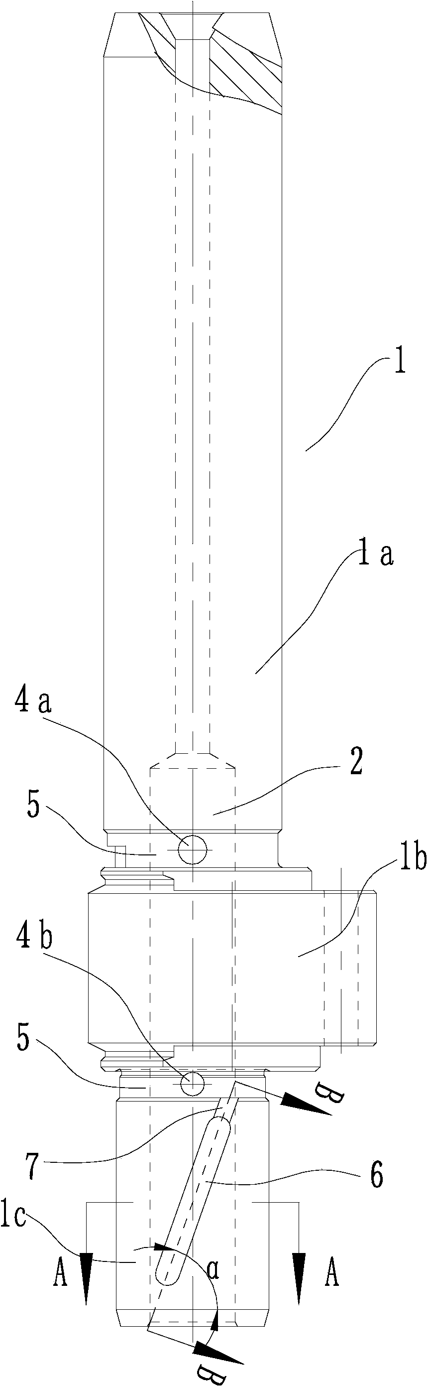
[0032] A self-lubricating crankshaft such as Figure 3 to Figure 5 As shown, the crankshaft 1 includes a major semi-axis 1a, an eccentric circle 1b and a minor semi-axis 1c. The eccentric circle 1b is located between the major semi-axis 1a and the minor semi-axis 1c, and an axial passage Hole 2, the top and bottom of the eccentric circle 1b are respectively provided with a first radial oil guide hole 4a and a second radial oil guide hole 4b communicating with the through hole 2, and the top and bottom of the eccentric circle 1b of the crankshaft 1 are respectively provided with a ring The tool relief groove 5, the first radial oil guide hole 4a and the second radial oil guide hole 4b are set in the annular tool relief groove 5; the oil in the through hole 2 passes through the first radial oil guide hole 4a and the second radial guide hole 4a. The oil hole 4b sprays oil to lubricate the main bearing assembled on the long semi-shaft and the auxiliary bearing assembled on the sho...

Embodiment 2

[0035] Such as Figure 6 to Figure 8 As shown, the difference from Embodiment 1 is that the lower end of the spiral oil guide groove 6 in the axial direction forms a slot 8 that runs through the entire inner wall surface of the through hole 2 and the outer surface of the short semi-shaft 1c of the crankshaft 1, and along the axial direction of the crankshaft 1 An inclined surface is formed between the upper edge of the groove hole 8 in the direction and the bottom end of the spiral communication groove 6, which changes the oil pumping direction of the bottom surface of the spiral oil guide groove 6, so that the oil pump pressure is stronger and the oil pump effect is better. At the same time, the angle range of the angle γ' formed between the lower end surface of the slotted hole 8 and the center line of the through hole 2 of the short half shaft 1c of the crankshaft 1 is preferably 50° to 70°, which is also convenient for the impurities produced by the wear and tear of the cra...

Embodiment 3

[0037] Such as Figure 9 to Figure 11As shown, the difference from Embodiment 1 is that the upper and lower ends of the spiral oil guide groove 6 in the axial direction respectively form a communication hole 9 that runs through the entire inner wall surface of the through hole 2 and the outer surface of the short half shaft 1c of the crankshaft 1, and the spiral oil guide groove The bottom surface of 6 is arranged parallel to the axial direction, and the through hole 2 leads to the spiral oil guide groove 6 through two communication holes 9, so as to selectively pump oil to different parts of the short half shaft 1c of the crankshaft 1, the pump oil pressure is strong, and the oil pump effect is good . In addition, the angle γ″ formed by the lower end surface of each communication hole 9 and the center line of the through hole 2 at the short half axis of the crankshaft 1 is preferably 50° to 70°, which is also convenient for impurities produced by the wear of the crankshaft an...


PUM


Abstract

The invention discloses a self-lubricating crankshaft which comprises a major semi-axis, an eccentric circle and a minor semi-axis. The center of the crankshaft is provided with an axial through hole; the top and the bottom of the eccentric circle are respectively provided with a first radial oil guide hole and a second rail oil guide hole which are communicated with the through hole; the outer surface of the minor semi-axis is provided with at least one spiral oil guide slot which is slantingly formed along the axial direction and is communicated with the through hole; the rotating direction of the spiral oil guide slot is opposite to that of the crankshaft; the outer surface of the minor semi-axis is also provided with a spiral communication groove extending towards the bottom of the eccentric circle from the top end of the spiral oil guide slot; the spiral communication groove does not run through the lower end face of the minor semi-axis; the spiral oil guide slot is spirally formed by using the center line of the crankshaft as the center; a helix angle alpha of the spiral oil guide slot has an angle range of 5 degrees to 85 degrees; a concave included angle beta of two opposite lateral surfaces of the spiral oil guide slot in the process of ascending along the spiral direction has an angle range of 2 degrees to 80 degrees; and the rotating direction of the spiral communication groove is the same with that of the spiral oil guide slot. The invention also discloses a rotary compressor, an air conditioner and a heat-pump water heater which use the self-lubricating crankshaft.

Description

【Technical field】 [0001] The invention relates to a crankshaft of a rotary compressor, in particular to a self-lubricating crankshaft and a rotary compressor, an air conditioner and a heat pump water heater using the crankshaft. 【Background technique】 [0002] Existing rotary compressors mainly rely on the oil guide plate installed on the inner side of the lower part of the crankshaft to supply oil. For compressors dedicated to heat pump water heaters, compressors that operate for a long time under harsh working conditions such as T3, and inverter compressors that operate at low frequencies, often Insufficient oil supply to the crankshaft, thin lubricating oil film will easily cause reliability problems such as severe wear and even jamming of the main and auxiliary friction pairs of the compressor crankshaft and eccentric circle; at the same time, after the compressor has been running for a period of time, the crankshaft main Parts are worn to a certain extent and even impur...

Claims


Application Information

Patent Timeline
Patent Type & Authority Applications(China)
IPC IPC(8): F04C29/02F16C3/14
Inventor 罗泽良
Owner ZHUHAI LANDA COMPRESSOR
Why Eureka
Try Eureka