
Level shift device

A technology of level shifting and voltage level, which is applied in the direction of logic circuit connection/interface layout, electrical components, electric pulse generation, etc., can solve the problems of chip price increase and power consumption increase, and achieve reduced power consumption, reduced size, Effect of preventing Vgs breakdown phenomenon

Inactive Publication Date: 2014-03-26
LSIS CO LTD
View PDF9 Cites 12 Cited by
  • Summary
  • Abstract
  • Description
  • Claims
  • Application Information

AI Technical Summary

Problems solved by technology

[0004] In a latch type level shifter generally used in gate drive circuits according to the related art, not only power consumption increases due to static current and rising conduction delay, but also chip price increases due to increase in chip size

Method used


Image

  • Level shift device
  • Level shift device
  • Level shift device

Examples


Embodiment Construction

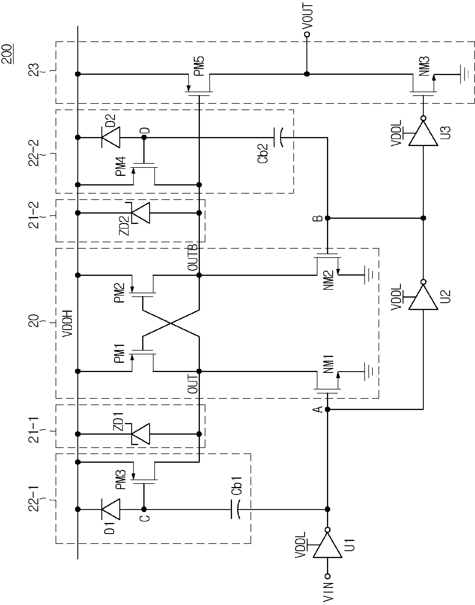
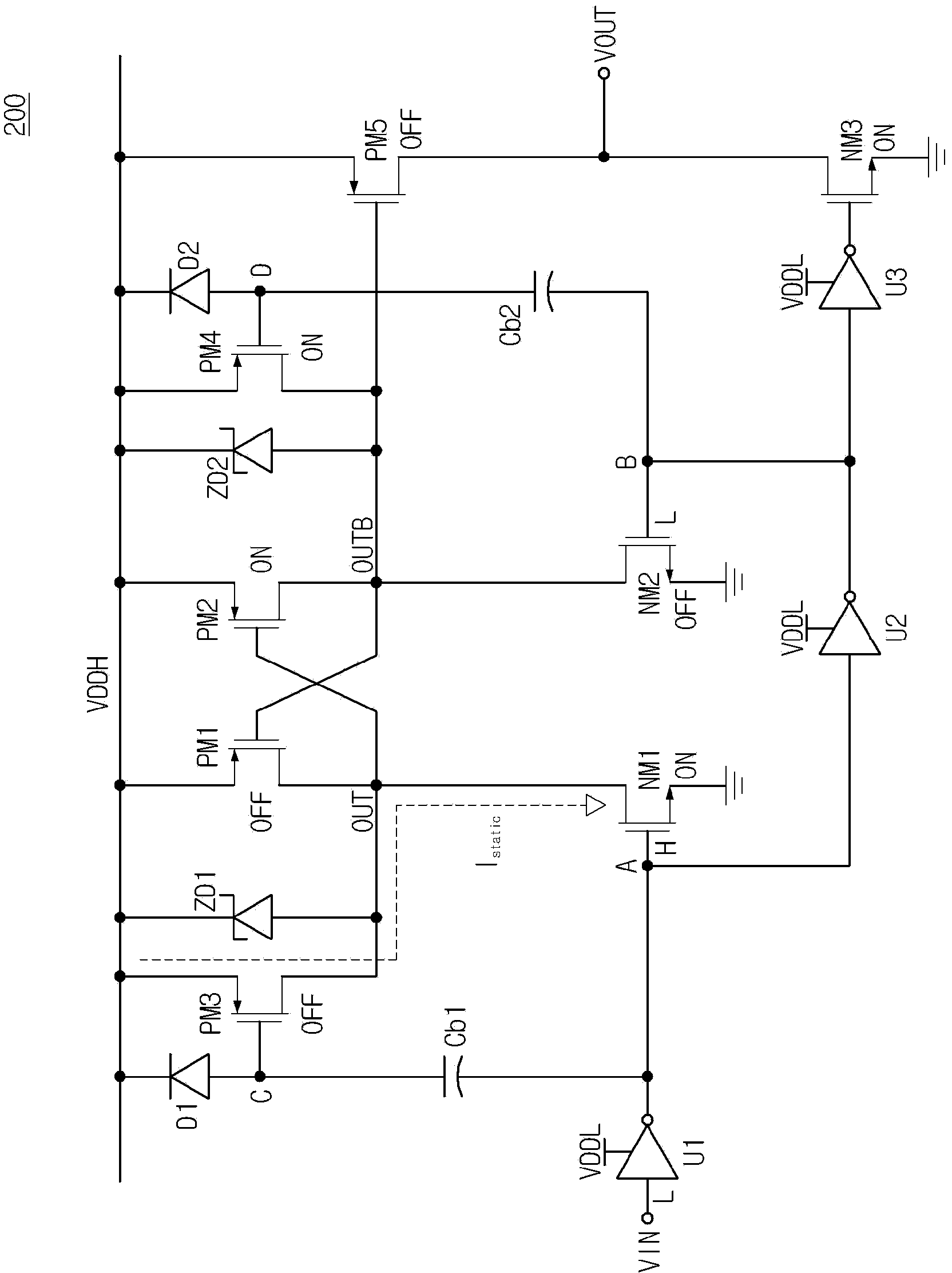
[0021] Hereinafter, a level shifting device according to an embodiment will be described in more detail with reference to the accompanying drawings. In the following description, only the suffixes "module" and "unit" are added to facilitate the description of the specification, and they can be used compatible with each other.

[0022] In the following description, when a component is connected to another component, it not only means that the components are directly connected to each other, but also may mean that the components are electrically connected to each other with another component interposed therebetween.

[0023] figure 1 is a circuit diagram showing a level shifting device according to one embodiment.

[0024] Such as figure 1 As shown in , the level shifting device 100 according to one embodiment includes a NOT gate U1 , a NOT gate U2 , and a latch-type level shifting unit 10 . The latch type level shift unit 10 includes a first NMOS NM1 and a second NMOS NM2 pe...


PUM


Abstract

Disclosed is a level shift device. The level shift device to convert an input signal having a low-voltage level into an output signal having a high-voltage level includes a latch-type level shifter and a voltage generator. The latch-type level shifter includes two upper pull-up P channel transistors and two lower P channel transistors to prevent the gate-source voltage breakdown of the two upper pull-up P channel transistors. The two upper pull-up P channel transistors and the two lower P channel transistors form a latch structure. The voltage generator generates a voltage to prevent the gate-source voltage brake down of the two upper pull-up P channel transistors and provides the voltage to the gate electrodes of the two lower P channel transistors.

Description

[0001] This application claims priority from Korean Patent Application No. 10-2012-0098498 (filed Sep. 5, 2012), which is hereby incorporated by reference in its entirety. Background technique [0002] Embodiments relate to a level shifter converting a low voltage level input signal into a high voltage level output signal and a gate driving device of an insulated gate bipolar transistor (IGBT) including the level shifter. [0003] Generally, in an insulated gate bipolar transistor (IGBT), if the gate voltage is not a sufficiently large voltage of 13V or less, the saturation voltage VCE_SAT of the device increases. If the gate voltage is a significantly low voltage of 10V or less, the IGBT operates in an active region, so that the device may be overheated and damaged. Accordingly, in order to prevent the device from overheating and damage, the gate drive circuit for driving the IGBT includes a level shift unit to convert a low voltage level input signal (in the range of 3.3V to...

Claims


Application Information

Patent Timeline
Patent Type & Authority Applications(China)
IPC IPC(8): H03K19/0185
CPCH03K3/356113H03K3/01G09G3/20H03K19/0185
Inventor 郑在锡
Owner LSIS CO LTD
Learn More