Method for producing timepiece spring, device for producing timepiece spring, timepiece spring, and timepiece
A manufacturing method and technology for timepieces, which are applied in the manufacture of watch springs and manufacturing devices, watch springs and watch fields, can solve the problems of reduced bending fatigue characteristics, easy entry into pinholes, difficult hardness, etc., and achieve improved bending fatigue characteristics, Eliminates the reduction of bending fatigue characteristics and the effect of reducing pinholes
- Summary
- Abstract
- Description
- Claims
- Application Information
AI Technical Summary
Problems solved by technology
Method used
Image
Examples
no. 1 approach
[0074] Next, a first embodiment of the present invention will be described with reference to the drawings.
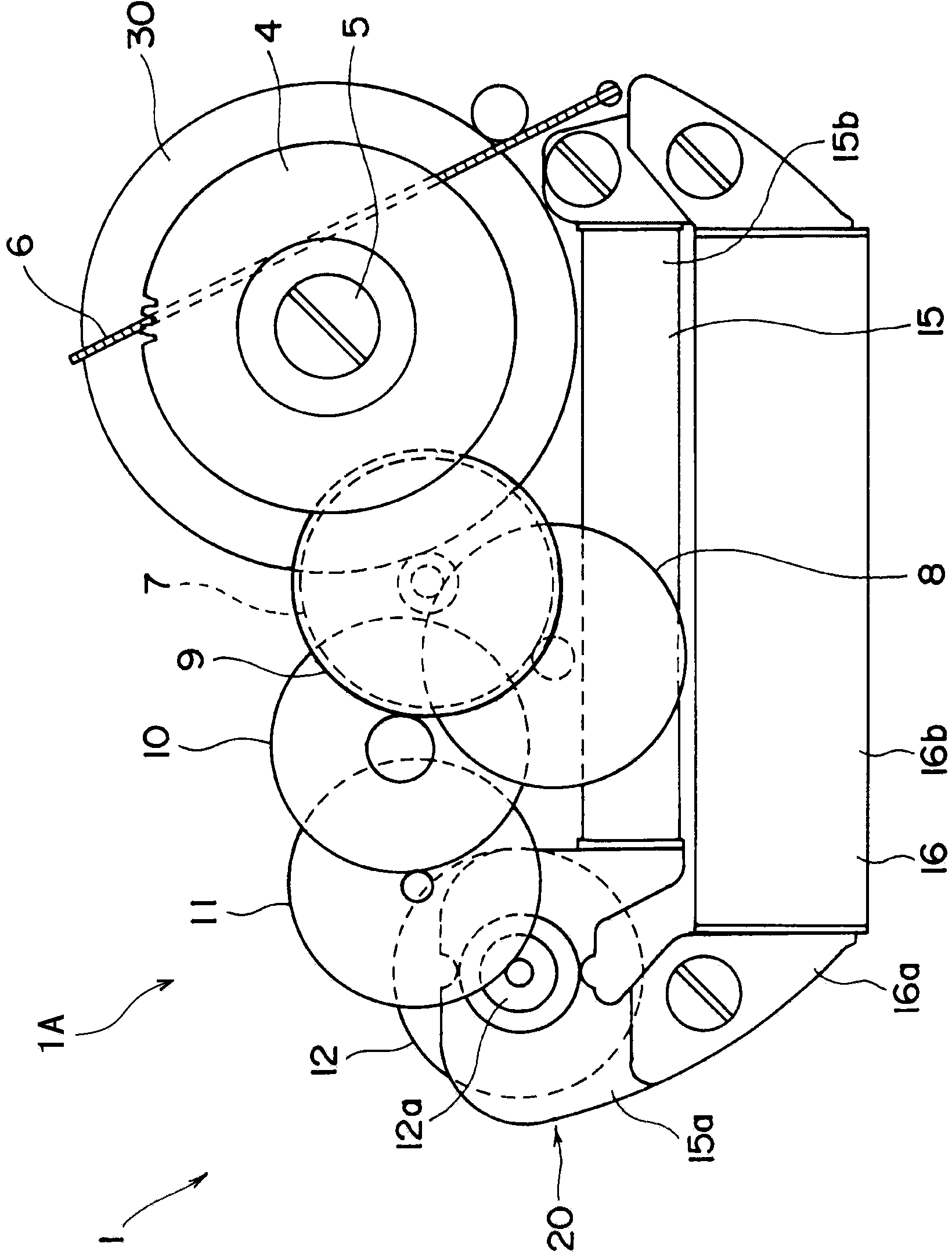
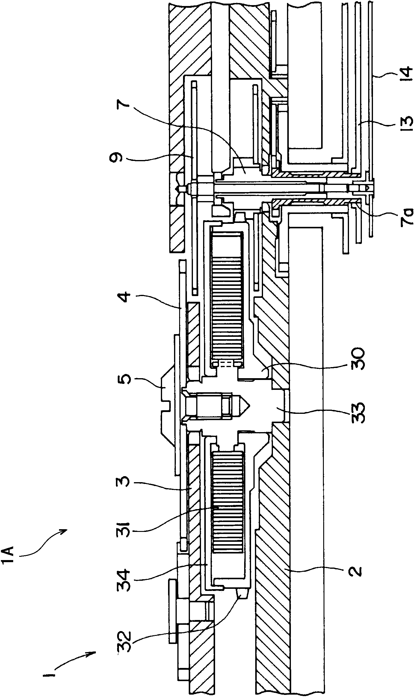
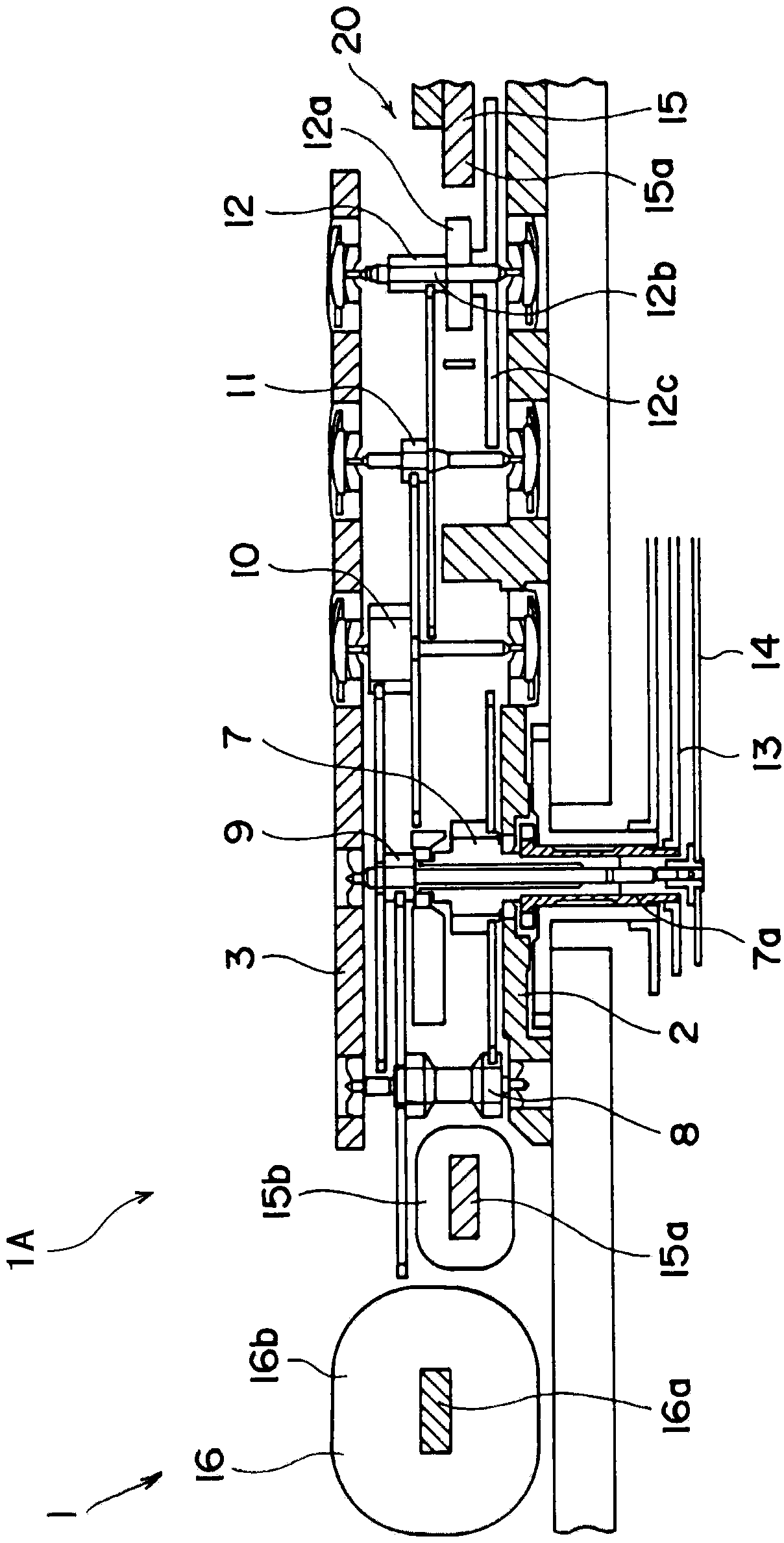
[0075] The first embodiment relates to the use of the timepiece spring of the present invention as a drive mechanism for a mainspring. figure 1 It is a plan view showing a drive mechanism 1A of an electronically controlled mechanical timepiece 1 using a spring made of a metallic glass plate according to the first embodiment of the present invention. figure 2 yes figure 1 Cross-sectional view of the drive mechanism 1A. image 3 yes figure 1 Another cross-sectional view of the drive mechanism 1A.
[0076] The drive mechanism 1A of the electronically controlled mechanical timepiece 1 has a barrel 30 composed of a metallic glass spring 31 , a barrel gear 32 , a barrel shaft 33 , and a barrel cover 34 .
[0077] The outer end of metallic glass spring 31 is fixed on the barrel gear 32 , and the inner end is fixed on the barrel shaft 33 . The barrel shaft 33 is supported...
no. 2 approach
[0141] In the above-mentioned first embodiment, as the metallic glass blank 100 of the sheet material 106 for manufacturing the metallic glass spring 31, the sheet material 101 produced by the single-roll liquid quenching method was used, but in this embodiment, the A thread-like material produced by spinning in a liquid. Next, the spinning in-liquid spinning method will be described.
[0142] [Spinning method in spinning solution]
[0143] Figure 10 It is a schematic diagram showing the configuration of the submerged spinning device 120 used in the production of the thread-shaped material 131 .
[0144] Figure 10 The spinning device 120 shown in the rotating liquid has: a rotatable cylindrical body 121; a quartz tube 122 having a nozzle 122a at the lower end and capable of accommodating a metallic glass raw material 122b inside; Frequency heating coil 123.
[0145] In addition, on both surfaces of the cylindrical body 121 , non-illustrated outflow prevention plates for...
no. 3 approach
[0165] Figure 12 It is a schematic diagram showing the rolling process of the manufacturing method of providing the convex part 144a and the concave part 145a in the pair of roll 144,145 in 3rd Embodiment.
[0166] In the above-mentioned first embodiment, a pair of rolls 104 and 105 with flat outer peripheral surfaces were used for the description, but in the present embodiment, the metal glass material in a superplastic state is sandwiched between the protrusions and the recesses during rolling. .
[0167] Such as Figure 12As shown, a convex portion 144a is provided at a predetermined position on the outer peripheral surface of one roll 144 of a pair of rolls 144 and 145 serving as a rolling unit 143 used in rolling processing. Further, a concave portion 145 a to be fitted into the convex portion 144 a is provided at a position facing the convex portion 144 a on the outer peripheral surface of the other roller 145 .
[0168] During the rolling, the metallic glass blank 1...
PUM
| Property | Measurement | Unit |
|---|---|---|
| glass transition temperature | aaaaa | aaaaa |
| crystallization temperature | aaaaa | aaaaa |
| Vickers hardness | aaaaa | aaaaa |
Abstract
Description
Claims
Application Information
 - Generate Ideas
- Intellectual Property
- Life Sciences
- Materials
- Tech Scout
- Unparalleled Data Quality
- Higher Quality Content
- 60% Fewer Hallucinations
Browse by: Latest US Patents, China's latest patents, Technical Efficacy Thesaurus, Application Domain, Technology Topic, Popular Technical Reports.
© 2025 PatSnap. All rights reserved.Legal|Privacy policy|Modern Slavery Act Transparency Statement|Sitemap|About US| Contact US: help@patsnap.com


