Eureka AIR delivers breakthrough ideas for toughest innovation challenges, trusted by R&D personnel around the world.

Stretcher-like terahertz wave polarization beam splitter

A polarizing beam splitter and terahertz technology, applied in the direction of instruments, light guides, optics, etc., can solve the problems of complex structure, expensive, bulky, etc., and achieve the effect of simple and compact structure, easy processing, and high beam splitting rate

Inactive Publication Date: 2014-03-26
CHINA JILIANG UNIV
View PDF5 Cites 2 Cited by
  • Summary
  • Abstract
  • Description
  • Claims
  • Application Information

AI Technical Summary

Problems solved by technology

[0003] In recent years, the research on terahertz wave functional devices has been gradually carried out at home and abroad. The terahertz wave polarization beam splitter is a very important terahertz wave device, which is used to manipulate and control the terahertz wave in the terahertz wave system. At present, Many scientific research institutions at home and abroad are committed to this research and have made some progress, but the terahertz wave polarization beam splitter is the focus and difficulty in the research of terahertz wave functional devices, and its existing research results and progress are still very limited. , the existing terahertz polarization beam splitters are often complex in structure, bulky, difficult to manufacture and expensive, so it is necessary to design a terahertz polarization beam splitter with simple and compact structure, small size, light weight and high beam splitting efficiency To meet the needs of future terahertz wave technology applications

Method used


Image

  • Stretcher-like terahertz wave polarization beam splitter
  • Stretcher-like terahertz wave polarization beam splitter
  • Stretcher-like terahertz wave polarization beam splitter

Examples


Embodiment 1

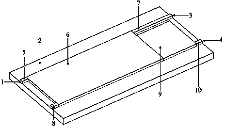
[0014] The substrate of the stretcher-shaped terahertz wave polarizing beam splitter has a length of 1000 μm, a width of 100 μm, and a thickness of 60 μm. The size parameters of the first rectangular plate and the second rectangular plate are the same, the length is 8 μm, the width is 4 μm, and the thickness is 60 μm. The third rectangular flat plate has a length of 140 μm, a width of 60 μm, and a thickness of 60 μm. The fourth rectangular flat plate has a length of 52 μm, a width of 4 μm, and a thickness of 60 μm. The fifth rectangular flat plate has a length of 44 μm, a width of 50 μm, and a thickness of 60 μm. The sixth rectangular flat plate has a length of 8 μm, a width of 4 μm, and a thickness of 60 μm. The material of the substrate is silicon dioxide. Materials of the first rectangular plate, the third rectangular plate, the fourth rectangular plate, the second rectangular plate, the fifth rectangular plate and the sixth rectangular plate are all high resistance sili...


PUM


Abstract

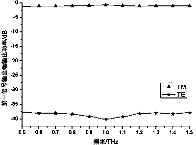
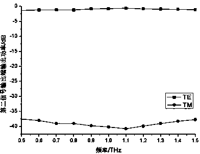
The invention discloses a stretcher-like terahertz wave polarization beam splitter comprising a signal input end, a substrate, a first signal output end, and a second signal output end. A first rectangular flat board, a third rectangular flat board, a fourth rectangular flat board, a second rectangular flat board, a fifth rectangular flat board, and a sixth rectangular flat board are arranged on the upper surface of the substrate. The right end of the fourth rectangular flat board is provided with the first signal output end. The right side of the lower end of the third rectangular flat board is connected with the left end of the fifth rectangular flat board. The right end of the fifth rectangular flat board is connected with the left end of the sixth rectangular flat board. The right end of the sixth rectangular flat board is provided with the second signal output end. Terahertz signals are input from the signal input end; the first signal output end outputs TM wave; the second signal output end outputs TE wave; the third rectangular flat board and the fourth rectangular flat board function in multiple-mode interference so as to achieve polarization beam splitting for terahertz signals. The stretcher-like terahertz wave polarization beam splitter has the advantages of simple, compact structure, small size, high splitting rate, convenience of manufacture and the like.

Description

technical field [0001] The invention relates to a terahertz wave polarization beam splitter, in particular to a stretcher-shaped terahertz wave polarization beam splitter. Background technique [0002] Terahertz technology is a new technology developed in the late 1980s. The terahertz frequency domain refers to the frequency between 0.1THz and 10THz. The unique frequency range of terahertz waves (between the microwave frequency band and the optical frequency band) covers the molecular vibration and rotation spectra of most macromolecular substances. Regardless of its absorption spectrum, reflection spectrum or emission spectrum, the frequency band has obvious fingerprint spectrum characteristics, which is not available in microwave. In addition, terahertz waves can penetrate most substances to varying degrees, which is not available for infrared radiation. These characteristics determine the value of terahertz technology. The ever-growing terahertz wave technology has grea...

Claims


Application Information

Patent Timeline
Patent Type & Authority Applications(China)
IPC IPC(8): G02B6/126
Inventor 李九生
Owner CHINA JILIANG UNIV
Why Eureka
Eureka Blog
Learn More