
Method for preparing carbon nanotube film

A carbon nanotube film and carbon nanotube technology are applied in the field of carbon nanotube film preparation, which can solve the problems of pattern defects, small beam size, and long time consumption.

Inactive Publication Date: 2014-03-12
TOP NANOSYS
View PDF2 Cites 6 Cited by
  • Summary
  • Abstract
  • Description
  • Claims
  • Application Information

AI Technical Summary

Problems solved by technology

In this way, the beam size is so small that it takes a long time to form a large-scale pattern and often produces pattern defects
[0007] And it is another problem to use separate dry etching equipment other than conventional wet etching equipment when forming carbon nanotube patterns by using dry etching

Method used


Image

  • Method for preparing carbon nanotube film
  • Method for preparing carbon nanotube film
  • Method for preparing carbon nanotube film

Examples


Embodiment approach

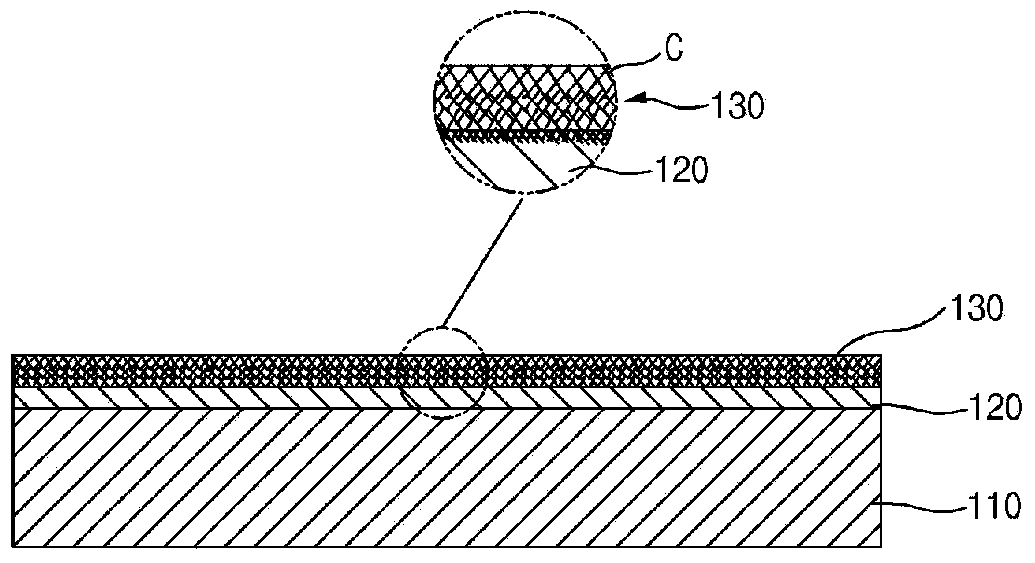
[0048] Embodiments are not limited to etch paste application methods or photoresist methods, and if some methods are melting away the etch target area E in the top adhesive layer 140, CNT coating layer 130, and base adhesive layer 120 ), then this method is also applicable to the concept of the present invention.

[0049] According to an exemplary embodiment, the CNT coating layer 130 is patterned by wet etching. Therefore, conventional wet etching equipment for patterning electrodes such as ITO may be applicable. Moreover, it can be etched quickly, and can form a fine pattern width.

[0050] Figure 7 is a flowchart illustrating a method of preparing a carbon nanotube film according to another exemplary embodiment of the present inventive concept. like Figure 7 As shown, the method S200 for preparing a carbon nanotube film includes, forming a CNT coating S210 comprising carbon nanotubes on a substrate, forming a wet-etched top adhesive layer S220 on the CNT coating, and ...


PUM


Abstract

The present invention provides a method for preparing a carbon nanotube film which can be wet-etched. The method for preparing a carbon nanotube film, according to the present invention, comprises the steps of: forming a base binder layer including a material which can be wet-etched, on a substrate; forming a CNT coating layer including carbon nanotube, on the upper surface of the base binder layer; forming a top binder layer including a material which can be wet-etched, on the upper surface of the CNT coating layer; and removing the regions to be etched of the CNT coating layer, the top binder layer, and the base binder layer through wet-etching.

Description

technical field [0001] Embodiments relate to a method of preparing a carbon nanotube film, and more particularly, to a carbon nanotube film applicable to various industrial sectors such as electrification, display, optical industry, etc. by forming a desired carbon nanopattern on a substrate method of preparation. Background technique [0002] Typically, transparent conductive films have high conductivity (eg, surface resistance below 1×10 3 Ω / sq) and high permeability (greater than 80%). Therefore, transparent conductive films are being used for antistatic films of automobile glass or architectural glass, transparent electromagnetic wave shielding materials such as electromagnetic wave shielding materials, and transparent heating elements such as heat ray reflective films and refrigerated showcases, etc., and plasma display panels ( PDP), liquid crystal display (LCD), light emitting diode (LED), organic light emitting diode (OLED), touch screen, or electrodes of various l...

Claims


Application Information

Patent Timeline
IPC IPC(8): C01B31/02H01B1/04B82B3/00B82Y40/00
CPCH01B1/04B82Y30/00B82Y40/00C01B31/0226C01B31/02C01B32/16
Inventor 郑多情方闰荣金承烈
Owner TOP NANOSYS
Learn More