Valve plate grinding machine

A valve plate grinding machine and grinding disc technology, which is applied in the direction of grinding machine tools, grinding devices, metal processing equipment, etc., can solve the problems of poor quality and low efficiency, and achieve the goal of eliminating human factors, ensuring accuracy and consistency, and saving manpower Effect

Inactive Publication Date: 2014-03-12
JINAN MEIDE CASTING CO LTD
View PDF4 Cites 12 Cited by
  • Summary
  • Abstract
  • Description
  • Claims
  • Application Information

AI Technical Summary

Problems solved by technology

[0003] In order to overcome the disadvantages of low efficiency and poor quality of manually grinding the valve plate with sandpaper, the invention provides a valve plate grinder, which not only improves the grinding speed, but also can ensure the quality of the product after grinding

Method used


Image

  • Valve plate grinding machine
  • Valve plate grinding machine

Examples


Embodiment 1

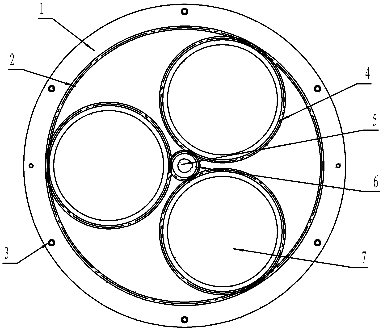
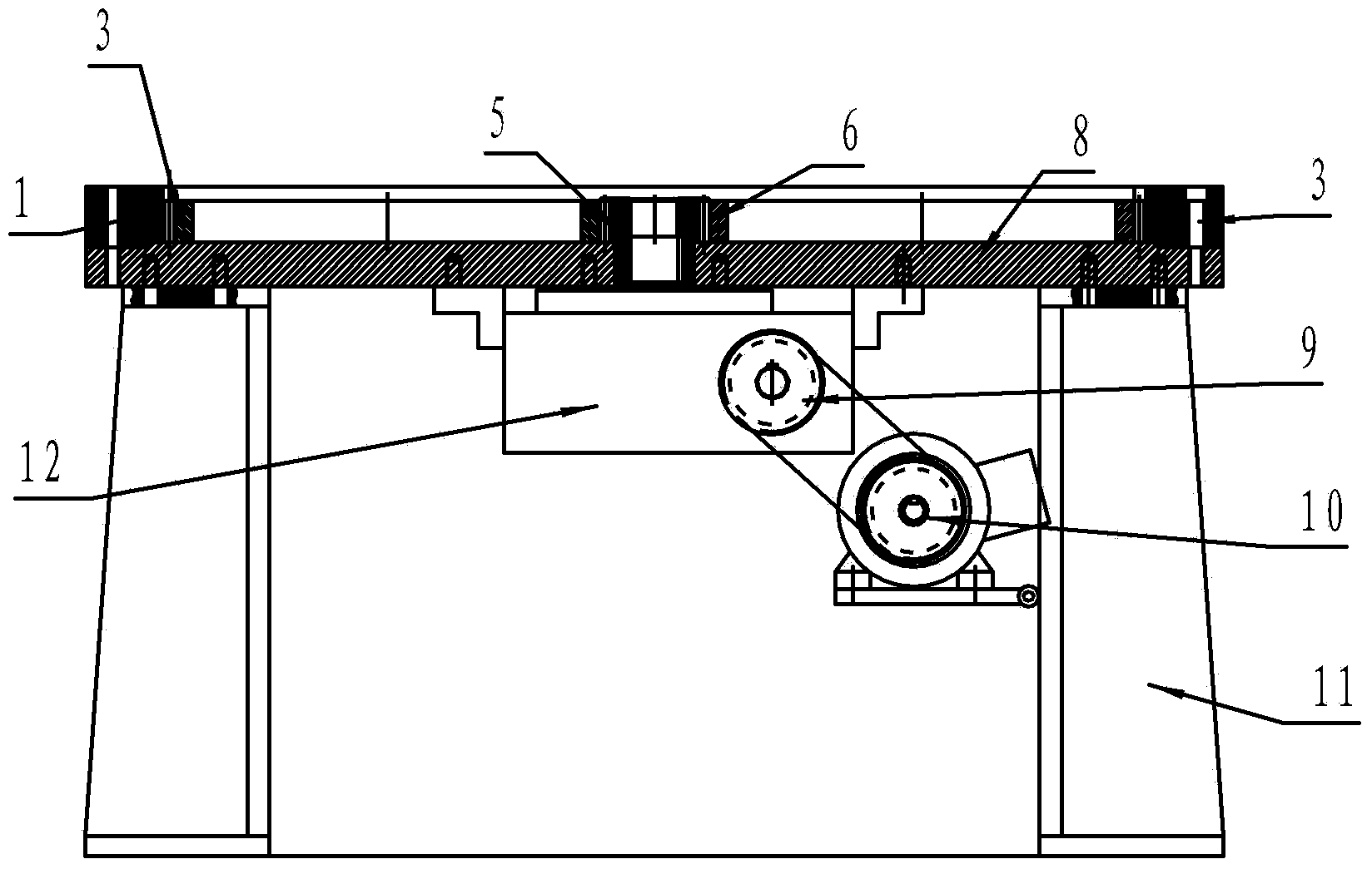
[0012] Embodiment 1, a valve plate grinding machine, is characterized in that: a grinding disc 8 is installed on the bracket 11, and the outer ring 1 with the internal ring gear 2 on the inner side is fixed by fixing bolts 3 around the upper surface of the grinding disc, and the center of the grinding disc Equipped with a central shaft 5, a central gear 6 is fixed on the shaft, 2-4 hollow planetary gear rings 4 are arranged in an array between the inner ring gear and the central gear, and the central shaft is connected with a reducer 12 installed on the bottom surface of the grinding disc. On the output shaft of the reducer, the drive wheel of the reducer and the output wheel of the motor are gears, the drive wheel of the reducer 9 is connected with the output wheel of the motor 10 fixed on the bracket through a chain, and the hollow part of the ring of the hollow planetary gear ring is placed as a valve plate District 7.

Embodiment 2

[0013] Embodiment 2, a valve plate grinder, is characterized in that: a grinding disc 8 is installed on the bracket 11, and the outer ring 1 with the internal ring gear 2 on the inner side is fixed by fixing bolts 3 around the upper surface of the grinding disc, and the center of the grinding disc is Equipped with a central shaft 5, a central gear 6 is fixed on the shaft, 2-4 hollow planetary gear rings 4 are arranged in an array between the inner ring gear and the central gear, and the central shaft is connected with a reducer 12 installed on the bottom surface of the grinding disc. On the output shaft of the reducer, the drive wheel of the reducer and the output wheel of the motor are pulleys, the drive wheel of the reducer 9 is connected with the output wheel of the motor 10 fixed on the bracket through a belt, and the hollow part of the ring of the hollow planetary gear ring is placed as a valve plate District 7.

[0014] The motor drives the main shaft of the reducer to r...


PUM


Abstract

The invention discloses a valve plate grinding machine, belongs to a grinding device and particularly belongs to a device utilizing a grinding plane in a star gear structure. According to the structure of the valve plate grinding machine, a grinding disc is mounted on a bracket, an outer ring is fixed at the periphery of the upper surface of the grinding disc, an inner gear ring is arranged on the inner side of the outer ring, a center shaft penetrates through the center of the grinding disc, a center gear is fixedly arranged on the center shaft, 2-4 planet gear rings distributed in an array manner are mounted between the inner gear ring and the center gear, the center shaft is mounted on an output shaft of a speed reducer mounted on the bottom surface of the grinding disc, and a speed reducer driving wheel is connected with a motor fixed on the bracket through a chain or a belt; the motor drives a main shaft of the speed reducer to rotate through a belt wheel so as to drive the center gear mounted on the main shaft of the speed reducer, the inner gear ring is fixed, and the center gear rotates to drive hollow planet gears to rotate around the main shaft of the speed reducer; valve plates are arranged in valve placement regions of the hollow planet gears, grinding sand is sprayed on the grinding disc, and the valve plates rotate along the hollow planet gears, so as to achieve a grinding purpose.

Description

technical field [0001] The invention belongs to grinding equipment, in particular to the equipment using a star wheel structure to grind planes. Background technique [0002] The main component of check valve products—the bonding surface between the valve plate and the valve body requires sealing. In order to improve the sealing performance, the bonding surface of the valve plate needs to be ground after processing. Since there is no special grinding equipment, the bonding surface is manually polished with sandpaper, which can neither guarantee production efficiency nor processing quality. Contents of the invention [0003] In order to overcome the disadvantages of low efficiency and poor quality of manual grinding of valve plates with sandpaper, the invention provides a valve plate grinder, which not only improves the grinding speed, but also can ensure the quality of the ground product. [0004] The technical solution adopted by the present invention to solve the techni...

Claims


Application Information

Patent Timeline
Patent Type & Authority Applications(China)
IPC IPC(8): B24B37/04
CPCB24B37/10
Inventor 于瑞水王宁张明一刘培安张维刚王启宝
Owner JINAN MEIDE CASTING CO LTD
Why Eureka
Try Eureka