
Method for testing heat insulation temperature of thermal barrier coating

A thermal barrier coating and coating technology, applied in the direction of material thermal development, material thermal conductivity, etc., can solve the problems of no comparison sample, short heating time, inability to test the thermal barrier coating thermal insulation temperature well, etc. Intuitive and precise thermal insulation effect

Active Publication Date: 2014-02-19
XI AN JIAOTONG UNIV
View PDF6 Cites 8 Cited by
  • Summary
  • Abstract
  • Description
  • Claims
  • Application Information

AI Technical Summary

Problems solved by technology

[0002] At present, the methods for measuring the thermal insulation performance of thermal barrier coatings by temperature difference method include: flame flow method, specifically spraying a layer of coating on the surface of graphite or other substrates, heating the surface of the sample with an oxyacetylene flame, and measuring the surface and back of the sample with a thermocouple The difference between the temperature before and after the sample is the heat insulation temperature. The disadvantage of this method is that there is no comparison sample, and the heating time is short, the temperature stability time of the surface and back of the sample is short, and it is also easily affected by the surrounding environment, so it cannot be tested well. Thermal barrier coating insulation temperature

Method used


Image

  • Method for testing heat insulation temperature of thermal barrier coating
  • Method for testing heat insulation temperature of thermal barrier coating
  • Method for testing heat insulation temperature of thermal barrier coating

Examples


Embodiment Construction

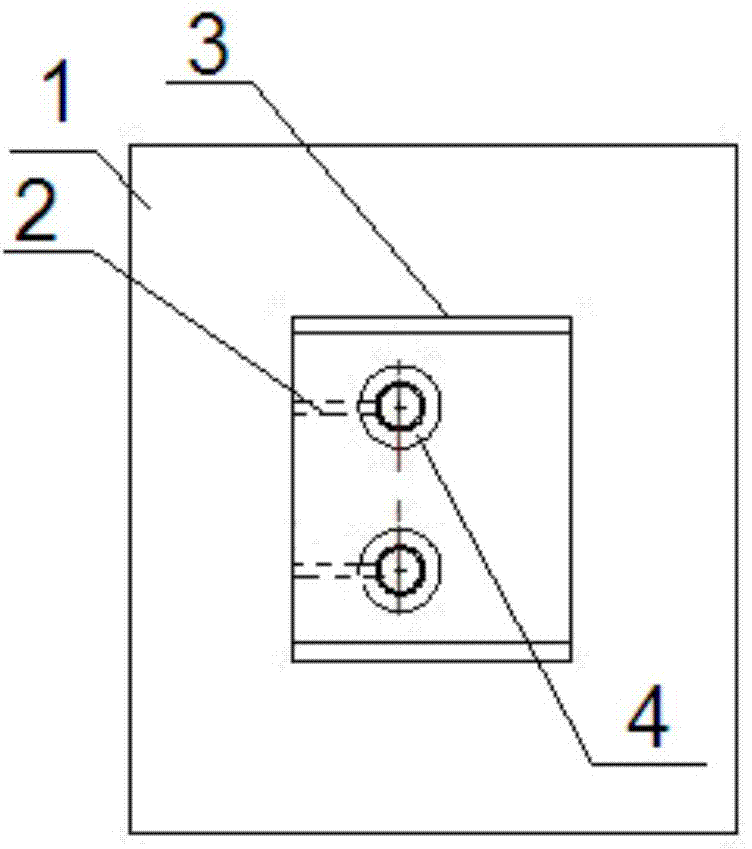
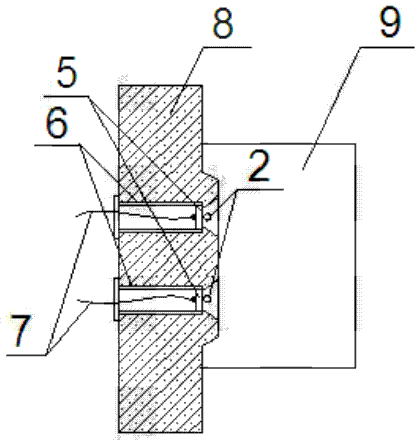
[0023] Such as figure 1 , figure 2 As shown, the experimental device of the present invention is a commonly used resistance furnace (the electric heating element can be a silicon carbon rod or a silicon molybdenum rod), and an improved heat-insulated furnace door is adopted, including a furnace door 1, and the furnace door insulation material 8 is fiber For aluminum silicate, a boss 3 is provided inside the furnace door (the side facing the furnace 9). Two through holes are drilled on the boss to the outside of the furnace door, and the ceramic tube 6 is embedded into the hole from the outside of the door. The sample 5 is installed in the The end of the ceramic tube 6 is fixed at the position of the bell mouth 4 close to the through hole. The bell mouth in front of the sample is provided with an S-type thermocouple 2 (passed through from the side of the boss 3), and a K-type thermocouple is welded at the center of the back of the sample. thermocouple7.

[0024] Prepare two ...


PUM

PropertyMeasurementUnit
diameteraaaaaaaaaa
thicknessaaaaaaaaaa

Abstract

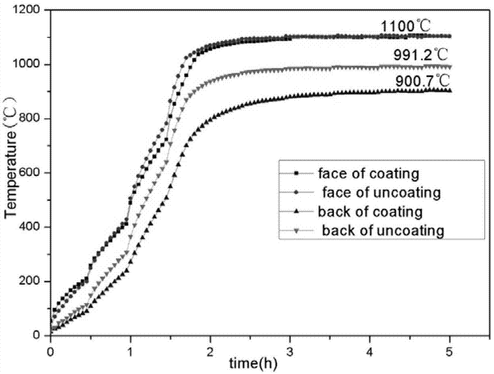
The invention discloses a method for testing heat insulation temperature of a thermal barrier coating. The method comprises the following steps: (1) respectively welding K-type thermocouples on backs of a coating sample and a coating-free sample of a same base material, and respectively and fixedly mounting the thermocouples in two through holes of an improved heat insulation furnace door of a resistance furnace, wherein the backs of the samples are directly contacted with the atmosphere, and the front surface of each sample faces a hearth; (2) mounting two S-shaped thermocouples on the heat insulation furnace door, wherein a contact of each S-shaped thermocouple is tightly attached to the front center of one sample; (3) electrifying and heating a resistance furnace, transmitting a temperature signal to a digital temperature recorder through the S-shaped thermocouples, stopping heating when the internal furnace temperature reaches 1100 DEG C and is stabilized for a period of time, performing furnace cooling on the samples, and drawing a temperature curve according to temperature data of the temperature recorder, wherein the heat insulation effect DeltaT of the thermal barrier coating is the difference of the back temperature of the coating-free sample and the back temperature of the coating sample.

Description

technical field [0001] The invention relates to a measurement technology for the thermal insulation performance of a thermal barrier coating, in particular to a measurement method for the thermal insulation temperature of the thermal barrier coating. Background technique [0002] At present, the methods for measuring the thermal insulation performance of thermal barrier coatings by temperature difference method include: flame flow method, specifically spraying a layer of coating on the surface of graphite or other substrates, heating the surface of the sample with an oxyacetylene flame, and measuring the surface and back of the sample with a thermocouple The difference between the temperature before and after the sample is the heat insulation temperature. The disadvantage of this method is that there is no comparison sample, and the heating time is short, the temperature stability time of the surface and back of the sample is short, and it is also easily affected by the surro...

Claims


Application Information

Patent Timeline
Patent Type & Authority Applications(China)
IPC IPC(8): G01N25/18G01N25/20
Inventor 韩志海白宇付倩倩唐健江刘琨强永明张利华
Owner XI AN JIAOTONG UNIV
Learn More