
Machine tool spindle device of numerically-controlled gear milling machine for spiral bevel gear

A technology of spiral bevel gears and tool spindles, which is applied in the direction of manufacturing tools, metal processing machinery parts, large fixed members, etc., can solve the problems of loss of transmission accuracy and transmission efficiency, limitation of the movement speed of tool spindles, affecting the machining accuracy of bevel gears, etc. Achieve the effect of improving machining accuracy and smoothness, improving machining accuracy, improving transmission accuracy and transmission stability

Active Publication Date: 2014-02-12
天津第一机床有限公司
View PDF9 Cites 3 Cited by
  • Summary
  • Abstract
  • Description
  • Claims
  • Application Information

AI Technical Summary

Problems solved by technology

This will not only lose transmission accuracy and transmission efficiency, but also limit the movement speed of the tool spindle
Due to the limitation of the tool spindle structure of the above-mentioned gear milling machine, at present, only the intermittent indexing method can be used to process spiral shrinking bevel gears and hypoid gears, but the continuous indexing method cannot be used to process cycloidal contour bevel gears and hypoid gears gear
Although the second-generation tool spindle structure using gear transmission has appeared in the past year, due to the influence of the machining accuracy of the gear itself, transmission errors are prone to occur, which in turn affects the machining accuracy of bevel gears.

Method used


Image

  • Machine tool spindle device of numerically-controlled gear milling machine for spiral bevel gear

Examples


Embodiment Construction

[0013] In order to further understand the invention content, characteristics and effects of the present invention, the following examples are given, and detailed descriptions are as follows in conjunction with the accompanying drawings:

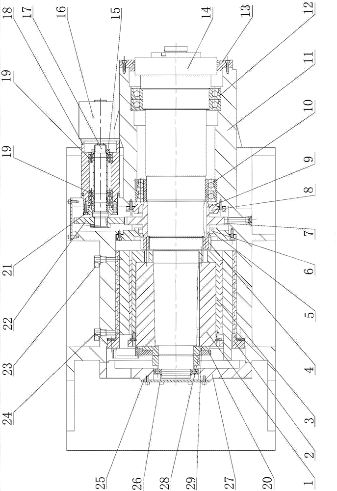
[0014] see figure 1 , CNC spiral bevel gear milling machine tool spindle device, including a spindle box 11 and a tool spindle 14 arranged in the spindle box. A torque motor stator 2 and a torque motor rotor 3 are fixed in the spindle housing, and the torque motor rotor 3 is fixed on the taper sleeve 1 located in the spindle housing, and is connected with the tool spindle through a flat key. The tool spindle is supported and fixed in the main shaft housing 11 and the casing back cover 27 by the front bearing 12, the rear bearing 10 and the auxiliary bearing. Cover 25. One end of the tool spindle is sealed by the front end cover 13, the other end of the tool spindle is equipped with an encoder 20 through a sleeve 29 and a third lock nut 28, ...


PUM


Abstract

The invention relates to a machine tool spindle device of a numerically-controlled gear milling machine for a spiral bevel gear. The machine tool spindle device comprises a spindle box body and a machine tool spindle arranged in the spindle box body. The machine tool spindle device is characterized in that a torque motor stator and a torque motor rotor are fixed into the spindle box body, the torque motor rotor is connected with the machine tool spindle through a taper sleeve and a key, a coder is installed at one end of the machine tool spindle through a sleeve and a locking nut, and a damping mechanism capable of applying opposite force to the middle portion of the machine tool spindle is installed on the middle portion of the machine tool spindle. The machine tool spindle device has the advantages that because the machine tool spindle is directly driven by a torque motor to rotate, loss, caused by transmission of a swinging table, of transmission precision and transmission efficiency can be avoided, and the motion speed of the machine tool spindle can be increased; the problem that due to the adoption of a gear transmission mechanism, machining precision can be affected, and transmission errors and large noise can easily occur can also be solved; in addition, opposite force is applied to the machine tool spindle by a hydraulic motor through gear transmission and plays a role in damping, and therefore transmission of the machine tool spindle is smoother and more reliable, and machining precision is improved.

Description

technical field [0001] The invention belongs to the technical field of gear machine tools, in particular to a tool spindle device of a numerically controlled spiral bevel gear milling machine. Background technique [0002] The CNC spiral bevel gear milling machine is used for high-speed and precise cutting of spiral bevel gears, improving the precision and smoothness of the tooth surface, meeting the requirements of stable transmission, reducing noise and improving precision. [0003] The tool spindle of the traditional gear milling machine is driven by a cradle, that is, the cutting tool (cutterhead) is fastened to the spindle of the cradle, and the cutterhead is installed in a certain position by means of the rotation of the eccentric drum of the cradle. This will not only lose transmission accuracy and transmission efficiency, but also limit the movement speed of the tool spindle. Due to the limitation of the tool spindle structure of the above-mentioned gear milling mac...

Claims


Application Information

Patent Timeline
IPC IPC(8): B23B19/02
CPCB23Q1/70
Inventor 王秀梅王景召柴宝连吴杰王威
Owner 天津第一机床有限公司
Learn More