Ultrasonic diagnostic apparatus and control program thereof

A diagnostic device, ultrasonic technology, applied in the direction of acoustic wave diagnosis, infrasonic wave diagnosis, ultrasonic/sonic wave/infrasonic wave diagnosis, etc., which can solve the problems of decreased receiving sensitivity, degradation of synthetic image quality, inability to include puncture needles, etc., and achieve good S/N Effect

Inactive Publication Date: 2014-02-12
GE MEDICAL SYST GLOBAL TECH CO LLC
View PDF7 Cites 2 Cited by
  • Summary
  • Abstract
  • Description
  • Claims
  • Application Information

AI Technical Summary

Problems solved by technology

[0005] However, in the ultrasonic diagnostic apparatus described in Patent Document 1, since the opening width in the elevation direction is reduced in order to widen the width of the ultrasound beam in the elevation direction, the receiving sensitivity decreases accordingly.
Therefore, there is concern about the quality degradation of the composite image
[0006] In addition, even if the opening is adjusted, the focus position in the depth direction does not change, and there is a limit in the adjustment of the width of the ultrasonic beam, and there is a possibility that the puncture needle cannot be included.

Method used


Image

  • Ultrasonic diagnostic apparatus and control program thereof
  • Ultrasonic diagnostic apparatus and control program thereof
  • Ultrasonic diagnostic apparatus and control program thereof

Examples


Embodiment Construction

[0028] Below, based on Figure 1 to Figure 9 Embodiments of the present invention will be described. figure 1 The illustrated ultrasonic diagnostic apparatus 1 includes an ultrasonic probe 2 , a transmitting and receiving beamformer 3 , an echo data processing unit 4 , a display control unit 5 , a display unit 6 , an operation unit 7 , a control unit 8 , and a storage unit 9 .

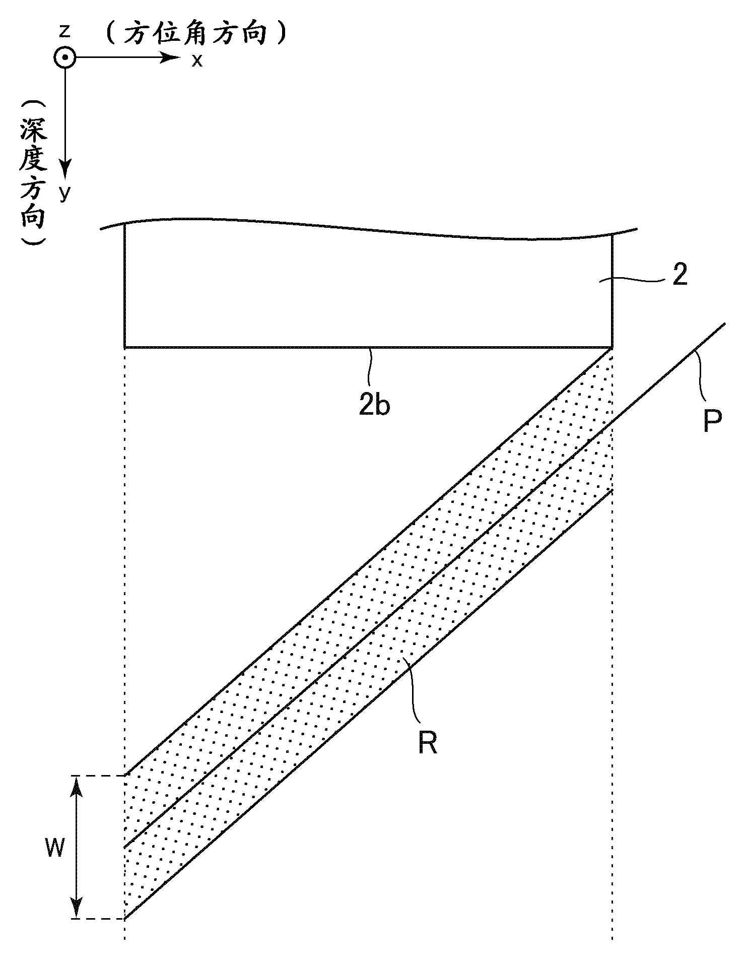
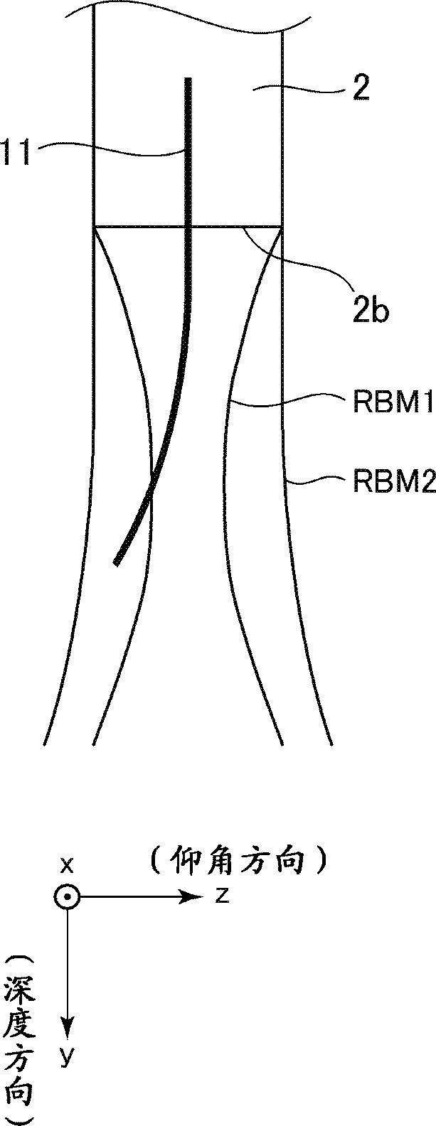
[0029] The ultrasonic probe 2 is as figure 2 As shown, it has a plurality of ultrasonic transducers 2 a arranged in an array, transmits ultrasonic waves to the subject through the ultrasonic transducers, and receives echo signals thereof. The plurality of ultrasonic transducers 2a are arranged in an azimuth direction (x direction) and an elevation direction (z direction).

[0030] Such as image 3 As shown, the front end side of the ultrasonic probe 2 is the irradiation surface 2b of ultrasonic waves. exist image 3 Although not shown in particular, the irradiation surface 2b may be formed of a c...


PUM


Abstract

An ultrasonic diagnostic apparatus is provided. The ultrasonic diagnostic apparatus includes an ultrasonic probe having plural ultrasonic transducers arranged in an elevation direction, a beamformer configured to form an ultrasonic reception beam by performing delay addition to an echo signal received by each of the ultrasonic transducers, and configured to form plural ultrasonic reception beams, each ultrasonic reception beam having a different width in the elevation direction, wherein the beamformer is configured to form the plural ultrasonic reception beams for one transmission / reception surface by adjusting a delay time in the delay addition, and a display control unit configured to display a synthetic image formed based upon the plural ultrasonic reception beams.

Description

technical field [0001] The present invention relates to an ultrasonic diagnostic device capable of changing the width of an ultrasonic receiving beam in an elevation direction and a control program thereof. Background technique [0002] In an ultrasonic diagnostic apparatus, an ultrasonic image of a subject can be displayed in real time. By making effective use of this real-time performance, when the puncture needle is inserted into the subject, the position of the puncture needle can be confirmed on real-time ultrasonic images. [0003] However, especially in the case of a thin puncture needle, the puncture needle may be bent halfway, and the puncture needle may go out of the range of the ultrasonic wave transmission and reception surface, that is, the ultrasonic beam formed by the ultrasonic probe. In this case, the puncture needle that is out of the range of the ultrasonic beam cannot be confirmed on the ultrasonic image. Therefore, in the ultrasonic diagnostic apparatu...

Claims


Application Information

Patent Timeline
Patent Type & Authority Applications(China)
IPC IPC(8): A61B8/00A61B8/08
CPCA61B8/0841A61B8/5207
Inventor 雨宫慎一野崎光弘
Owner GE MEDICAL SYST GLOBAL TECH CO LLC
Why Eureka
Try Eureka